 |
전자부품 데이터시트 검색엔진 |
|
|
전자부품 데이터시트 검색엔진 |
|
The question interval is too short.
Please try again in a few seconds.

Hello, Please ask a question about R3-PD16BS/Q Datasheet
# Example questions:
➢ How are do1-do8 related to the output circuit? explain what these represent in terms of functionality.
➢ If you wanted to control output 3 (do3), which pin on the bus connector would you interface with, and what type of signal would be required (high/low)?
➢ Describe the function of dip switches 1-8. what aspects of the device's operation do they control, if any?
| Part No. | R3-PD16BS/Q |
| Manufacturer | MSYSTEM |
| Size | 199 Kbytes |
| Pages | 8 pages |
| Description | Remote I/O R3 Series ONE-SHOT PULSE OUTPUT MODULE |

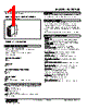
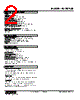
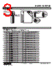
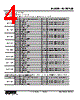



Okay, I've reviewed the documentation you provided. Here's a breakdown of what it tells us about the R-761WD module, combining information from all the extracts:
1. General Functionality:
️· The R-761WD is an I/O module.
️· It's a 16-channel module (16 I/O).
️· The documentation suggests it's used in a system where DIP switches are important for configuration.
️· LEDs provide status indication (RUN, ERR, and potentially an indicator LED).
2. Channel Mapping & Connections
️· Channels 1-16: These are the I/O channels.
- DO (Digital Output) and DI (Digital Input) assignment: This depends on the module's configuration.
- The module has a COM (Common) terminal.
️· Channel Assignment: The wiring diagrams show the connection for each channel.
️· Sequential connections: Channels are numbered sequentially from 1 to 16.
3. Configuration and DIP Switches:
️· DIP switches (labeled 1-8 in the diagrams) are used for configuration. The specific function of each DIP switch is *not* described in detail in the provided snippets.
️· It appears there are two sets of DIP switches (DIP 1-4 & DIP 5-8)
- Changing DIP switch positions alters the module's behavior (e.g., switching between DO and DI, potentially influencing other characteristics).
4. Status LEDs
️· RUN LED: Indicates the module is powered and attempting to operate correctly.
️· ERR LED: Signals an error condition. The cause of the error would need to be determined by referring to more detailed documentation.
️· Indicator LED: Its exact purpose isn't clear from these excerpts, but it is used to indicate certain channel states.
Important Caveats and Missing Information:
️· Specific DIP Switch Functions: The documentation *doesn't* explain what each individual DIP switch does. This is critical for configuring the module for specific applications. A full DIP switch configuration table is needed.
️· Module Power Requirements: No information is provided regarding the required power supply voltage, current consumption, or grounding.
️· Detailed Error Codes: The meaning of the ERR LED is unclear. Detailed error codes or a troubleshooting guide would be necessary to diagnose problems.
️· Module Type: Some parts mention "Communication Circuit Control Circuit" indicating an embedded system may be involved.
To fully understand and use the R-761WD module, you need to consult the full, comprehensive documentation that describes the functions of the DIP switches and provides error codes.
1. General Functionality:
️· The R-761WD is an I/O module.
️· It's a 16-channel module (16 I/O).
️· The documentation suggests it's used in a system where DIP switches are important for configuration.
️· LEDs provide status indication (RUN, ERR, and potentially an indicator LED).
2. Channel Mapping & Connections
️· Channels 1-16: These are the I/O channels.
- DO (Digital Output) and DI (Digital Input) assignment: This depends on the module's configuration.
- The module has a COM (Common) terminal.
️· Channel Assignment: The wiring diagrams show the connection for each channel.
️· Sequential connections: Channels are numbered sequentially from 1 to 16.
3. Configuration and DIP Switches:
️· DIP switches (labeled 1-8 in the diagrams) are used for configuration. The specific function of each DIP switch is *not* described in detail in the provided snippets.
️· It appears there are two sets of DIP switches (DIP 1-4 & DIP 5-8)
- Changing DIP switch positions alters the module's behavior (e.g., switching between DO and DI, potentially influencing other characteristics).
4. Status LEDs
️· RUN LED: Indicates the module is powered and attempting to operate correctly.
️· ERR LED: Signals an error condition. The cause of the error would need to be determined by referring to more detailed documentation.
️· Indicator LED: Its exact purpose isn't clear from these excerpts, but it is used to indicate certain channel states.
Important Caveats and Missing Information:
️· Specific DIP Switch Functions: The documentation *doesn't* explain what each individual DIP switch does. This is critical for configuring the module for specific applications. A full DIP switch configuration table is needed.
️· Module Power Requirements: No information is provided regarding the required power supply voltage, current consumption, or grounding.
️· Detailed Error Codes: The meaning of the ERR LED is unclear. Detailed error codes or a troubleshooting guide would be necessary to diagnose problems.
️· Module Type: Some parts mention "Communication Circuit Control Circuit" indicating an embedded system may be involved.
| Part No. | R3-PD16BS/Q |
| Manufacturer | MSYSTEM |
| Size | 199 Kbytes |
| Pages | 8 pages |
| Description | Remote I/O R3 Series ONE-SHOT PULSE OUTPUT MODULE |
| ALLDATASHEET 가 귀하에 도움이 되셨나요? [ DONATE ] |
Alldatasheet는? | 광고문의 | 운영자에게 연락하기 | 개인정보취급방침 | 링크 투 데이터시트 | 링크교환 | 제조사별 검색 All Rights Reserved©Alldatasheet.com |
| Russian : Alldatasheetru.com | Korean : Alldatasheet.co.kr | Spanish : Alldatasheet.es | French : Alldatasheet.fr | Italian : Alldatasheetit.com Portuguese : Alldatasheetpt.com | Polish : Alldatasheet.pl | Vietnamese : Alldatasheet.vn Indian : Alldatasheet.in | Mexican : Alldatasheet.com.mx | British : Alldatasheet.co.uk | New Zealand : Alldatasheet.co.nz |
|
Family Site : ic2ic.com |
icmetro.com |
 Korean ▼
  English
 Chinese
 German
 Japanese
 Russian
 Spanish
 French
 Italian
 Portuguese
 Polish
 Vietnamese
 Indian
 Mexican
 British
 New Zealand