 |
전자부품 데이터시트 검색엔진 |
|
|
전자부품 데이터시트 검색엔진 |
|
The question interval is too short.
Please try again in a few seconds.

Hello, Please ask a question about AP1635 Datasheet
# Example questions:
➢ What is the typical operating current (icc) of the ap1635 when no load is applied?
➢ What is the recommended feedback resistor ratio (r2/r1) for setting the output voltage?
➢ What is the minimum input voltage (vin) for the ap1635 to operate?
| Part No. | AP1635 |
| Manufacturer | DIODES |
| Size | 167 Kbytes |
| Pages | 8 pages |
| Description | PWM/PFM DUAL MODE STEP-DOWN DC/DC |


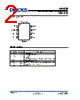
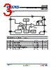
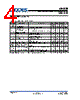
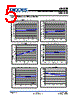


1. Overview & Purpose:
️· What it is: The AP1635 is a PWM (Pulse Width Modulation) and PFM (Pulse Frequency Modulation) mode step-down DC-DC converter. This means it efficiently converts a higher DC voltage into a lower DC voltage.
️· Application: It's designed for applications needing efficient voltage regulation, such as powering portable devices, microcontrollers, and other electronics.
️· Key Features:
- PWM/PFM Mode: Adapts operation for high efficiency at both light and heavy loads. PWM for heavier loads, PFM for light loads.
- Wide Input Voltage Range: Operates from 2.2V to 5V.
- Adjustable Output Voltage: The output voltage is determined by external resistors, allowing for flexibility in design.
- Current Limiting: Provides overcurrent protection.
- UVLO (Undervoltage Lockout): Prevents operation when the input voltage is too low, protecting the device.
- Standby Current Consumption: Low standby current for power-sensitive applications.
2. Electrical Specifications (Key Values):
️· Input Voltage (Vin): 2.2V to 5V
️· Output Voltage (Vout): Adjustable via external resistors (formula given: Vout = 1 * (1 + R2/R1))
️· Operating Frequency (Fosc): Approximately 700 kHz (can vary)
️· UVLO Voltage: 2V (minimum input voltage for operation)
️· Standby Current (ISTB): Around 6 μA
️· Current Limit (ICL): 1200mA to 1600mA (peak)
️· Efficiency (EFFI): Typically around 93% (dependent on load and input voltage)
3. Operational Modes & Features:
️· PWM Mode: Used at heavier loads. Provides good transient response and tight regulation.
️· PFM Mode: Used at light loads. Significantly improves efficiency by reducing switching losses. The PFM duty cycle ranges from 15% to 35%.
️· Adjustable Output Voltage: The output voltage can be adjusted by selecting appropriate resistor values for R1 and R2.
️· Current Limiting: Protects the circuit from excessive current draw.
️· UVLO: Prevents operation when the input voltage is too low, protecting the device and ensuring stable operation.
4. Typical Application Circuit:
️· A simplified schematic is provided showing the essential components:
- Input Voltage Source (2.2V to 5.5V)
- Inductor (10uH)
- AP1635 Converter
- Output Capacitor
- Feedback Resistors (R1 and R2)
️· The output voltage is calculated using the formula: Vout = 1 * (1 + R2/R1)
5. Marking Information:
️· The marking on the IC package indicates the part number, year of manufacture, week of manufacture, and an internal code. A "G" signifies Lead Free.
6. Package Information:
️· The AP1635 is available in a standard SO-8 package (SOP-8L). The datasheet provides dimensions and a recommended land pattern for proper PCB layout.
7. Important Notices:
️· Standard legal disclaimers regarding product changes, life support applications, and liability.
In essence, the AP1635 is a versatile and efficient DC-DC converter suitable for a wide range of portable electronic applications.
1. Overview & Purpose:
️· What it is: The AP1635 is a PWM (Pulse Width Modulation) and PFM (Pulse Frequency Modulation) mode step-down DC-DC converter. This means it efficiently converts a higher DC voltage into a lower DC voltage.
️· Application: It's designed for applications needing efficient voltage regulation, such as powering portable devices, microcontrollers, and other electronics.
️· Key Features:
- PWM/PFM Mode: Adapts operation for high efficiency at both light and heavy loads. PWM for heavier loads, PFM for light loads.
- Wide Input Voltage Range: Operates from 2.2V to 5V.
- Adjustable Output Voltage: The output voltage is determined by external resistors, allowing for flexibility in design.
- Current Limiting: Provides overcurrent protection.
- UVLO (Undervoltage Lockout): Prevents operation when the input voltage is too low, protecting the device.
- Standby Current Consumption: Low standby current for power-sensitive applications.
2. Electrical Specifications (Key Values):
️· Input Voltage (Vin): 2.2V to 5V
️· Output Voltage (Vout): Adjustable via external resistors (formula given: Vout = 1 * (1 + R2/R1))
️· Operating Frequency (Fosc): Approximately 700 kHz (can vary)
️· UVLO Voltage: 2V (minimum input voltage for operation)
️· Standby Current (ISTB): Around 6 μA
️· Current Limit (ICL): 1200mA to 1600mA (peak)
️· Efficiency (EFFI): Typically around 93% (dependent on load and input voltage)
3. Operational Modes & Features:
️· PWM Mode: Used at heavier loads. Provides good transient response and tight regulation.
️· PFM Mode: Used at light loads. Significantly improves efficiency by reducing switching losses. The PFM duty cycle ranges from 15% to 35%.
️· Adjustable Output Voltage: The output voltage can be adjusted by selecting appropriate resistor values for R1 and R2.
️· Current Limiting: Protects the circuit from excessive current draw.
️· UVLO: Prevents operation when the input voltage is too low, protecting the device and ensuring stable operation.
4. Typical Application Circuit:
️· A simplified schematic is provided showing the essential components:
- Input Voltage Source (2.2V to 5.5V)
- Inductor (10uH)
- AP1635 Converter
- Output Capacitor
- Feedback Resistors (R1 and R2)
️· The output voltage is calculated using the formula: Vout = 1 * (1 + R2/R1)
5. Marking Information:
️· The marking on the IC package indicates the part number, year of manufacture, week of manufacture, and an internal code. A "G" signifies Lead Free.
6. Package Information:
️· The AP1635 is available in a standard SO-8 package (SOP-8L). The datasheet provides dimensions and a recommended land pattern for proper PCB layout.
7. Important Notices:
️· Standard legal disclaimers regarding product changes, life support applications, and liability.
In essence, the AP1635 is a versatile and efficient DC-DC converter suitable for a wide range of portable electronic applications.
| Part No. | AP1635 |
| Manufacturer | DIODES |
| Size | 167 Kbytes |
| Pages | 8 pages |
| Description | PWM/PFM DUAL MODE STEP-DOWN DC/DC |
| ALLDATASHEET 가 귀하에 도움이 되셨나요? [ DONATE ] |
Alldatasheet는? | 광고문의 | 운영자에게 연락하기 | 개인정보취급방침 | 링크 투 데이터시트 | 링크교환 | 제조사별 검색 All Rights Reserved©Alldatasheet.com |
| Russian : Alldatasheetru.com | Korean : Alldatasheet.co.kr | Spanish : Alldatasheet.es | French : Alldatasheet.fr | Italian : Alldatasheetit.com Portuguese : Alldatasheetpt.com | Polish : Alldatasheet.pl | Vietnamese : Alldatasheet.vn Indian : Alldatasheet.in | Mexican : Alldatasheet.com.mx | British : Alldatasheet.co.uk | New Zealand : Alldatasheet.co.nz |
|
Family Site : ic2ic.com |
icmetro.com |
 Korean ▼
  English
 Chinese
 German
 Japanese
 Russian
 Spanish
 French
 Italian
 Portuguese
 Polish
 Vietnamese
 Indian
 Mexican
 British
 New Zealand