|
전자부품 데이터시트 검색엔진 |
|
|
전자부품 데이터시트 검색엔진 |
|
STM32F412RGU6PTR 데이터시트(PDF) 129 Page - STMicroelectronics |
|
|
|||||||||||||||||||||||||||||
STM32F412RGU6PTR 데이터시트(HTML) 129 Page - STMicroelectronics |
|
|
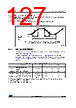
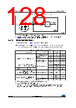
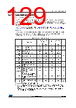
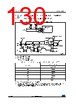
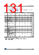
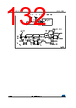
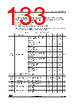
129 / 201 page  DocID028087 Rev 7 129/201 STM32F412xE/G Electrical characteristics 166 6.3.19 Communications interfaces I2C interface characteristics The I2C interface meets the requirements of the standard I2C communication protocol with the following restrictions: the I/O pins SDA and SCL are mapped to are not “true” open- drain. When configured as open-drain, the PMOS connected between the I/O pin and VDD is disabled, but is still present. The I2C characteristics are described in Table 62. Refer also to Section 6.3.16: I/O port characteristics for more details on the input/output alternate function characteristics (SDA and SCL). The I2C bus interface supports standard mode (up to 100 kHz) and fast mode (up to 400 kHz). The I2C bus frequency can be increased up to 1 MHz. For more details about the complete solution, contact your local ST sales representative. Table 62. I2C characteristics Symbol Parameter Standard mode I2C(1)(2) 1. Guaranteed by design, not tested in production. Fast mode I2C(1)(2) 2. fPCLK1 must be at least 2 MHz to achieve standard mode I2C frequencies. It must be at least 4 MHz to achieve fast mode I2C frequencies, and a multiple of 10 MHz to reach the 400 kHz maximum I2C fast mode clock. Unit Min Max Min Max tw(SCLL) SCL clock low time 4.7 - 1.3 - µs tw(SCLH) SCL clock high time 4.0 - 0.6 - tsu(SDA) SDA setup time 250 - 100 - ns th(SDA) SDA data hold time 0 3450(3) 3. The device must internally provide a hold time of at least 300 ns for the SDA signal in order to bridge the undefined region of the falling edge of SCL. 0900(4) tr(SDA) tr(SCL) SDA and SCL rise time - 1000 - 300 tf(SDA) tf(SCL) SDA and SCL fall time - 300 - 300 th(STA) Start condition hold time 4.0 - 0.6 - µs tsu(STA) Repeated Start condition setup time 4.7 - 0.6 - tsu(STO) Stop condition setup time 4.0 - 0.6 - µs tw(STO:STA) Stop to Start condition time (bus free) 4.7 - 1.3 - µs tSP Pulse width of the spikes that are suppressed by the analog filter for standard fast mode - - 50 120(5) ns Cb Capacitive load for each bus line - 400 - 400 pF |
|
링크 URL |
| ALLDATASHEET 가 귀하에 도움이 되셨나요? [ DONATE ] |
Alldatasheet는? | 광고문의 | 운영자에게 연락하기 | 개인정보취급방침 | 링크 투 데이터시트 | 링크교환 | 제조사별 검색 All Rights Reserved©Alldatasheet.com |
| Russian : Alldatasheetru.com | Korean : Alldatasheet.co.kr | Spanish : Alldatasheet.es | French : Alldatasheet.fr | Italian : Alldatasheetit.com Portuguese : Alldatasheetpt.com | Polish : Alldatasheet.pl | Vietnamese : Alldatasheet.vn Indian : Alldatasheet.in | Mexican : Alldatasheet.com.mx | British : Alldatasheet.co.uk | New Zealand : Alldatasheet.co.nz |
|
Family Site : ic2ic.com |
icmetro.com |
 Korean ▼
 English
 Chinese
 German
 Japanese
 Russian
 Korean
 Spanish
 French
 Italian
 Portuguese
 Polish
 Vietnamese
 Indian
 Mexican
 British
 New Zealand