|
전자부품 데이터시트 검색엔진 |
|
|
전자부품 데이터시트 검색엔진 |
|
STM32F412RGU6TR 데이터시트(PDF) 134 Page - STMicroelectronics |
|
|
|||||||||||||||||||||||||||||
STM32F412RGU6TR 데이터시트(HTML) 134 Page - STMicroelectronics |
|
|
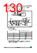
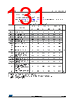
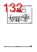
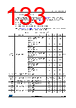
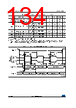
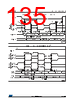
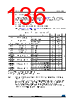
134 / 201 page  Electrical characteristics STM32F412xE/G 134/201 DocID028087 Rev 7 Figure 40. SPI timing diagram - slave mode and CPHA = 0 ta(SO) Data output access time Slave mode 7 - 21 ns tdis(SO) Data output disable time Slave mode 5 - 12 ns tv(SO) Data output valid time Slave mode (after enable edge), 2.7 V < VDD < 3.6 V -7.5 9 ns Slave mode (after enable edge), 1.7 V < VDD < 3.6 V -7.5 14 ns th(SO) Data output hold time Slave mode (after enable edge), 1.7 V < VDD < 3.6 V 5.5 - - ns tv(MO) Data output valid time Master mode (after enable edge) - 3 8 ns th(MO) Data output hold time Master mode (after enable edge) 2 - - ns 1. Guaranteed by characterization, not tested in production. 2. Maximum frequency in Slave transmitter mode is determined by the sum of tv(SO) and tsu(MI) which has to fit into SCK low or high phase preceding the SCK sampling edge. This value can be achieved when the SPI communicates with a master having tsu(MI) = 0 while Duty(SCK) = 50% Table 65. SPI dynamic characteristics(1) (continued) Symbol Parameter Conditions Min Typ Max Unit |
|
링크 URL |
| ALLDATASHEET 가 귀하에 도움이 되셨나요? [ DONATE ] |
Alldatasheet는? | 광고문의 | 운영자에게 연락하기 | 개인정보취급방침 | 링크 투 데이터시트 | 링크교환 | 제조사별 검색 All Rights Reserved©Alldatasheet.com |
| Russian : Alldatasheetru.com | Korean : Alldatasheet.co.kr | Spanish : Alldatasheet.es | French : Alldatasheet.fr | Italian : Alldatasheetit.com Portuguese : Alldatasheetpt.com | Polish : Alldatasheet.pl | Vietnamese : Alldatasheet.vn Indian : Alldatasheet.in | Mexican : Alldatasheet.com.mx | British : Alldatasheet.co.uk | New Zealand : Alldatasheet.co.nz |
|
Family Site : ic2ic.com |
icmetro.com |
 Korean ▼
 English
 Chinese
 German
 Japanese
 Russian
 Korean
 Spanish
 French
 Italian
 Portuguese
 Polish
 Vietnamese
 Indian
 Mexican
 British
 New Zealand