 |
전자부품 데이터시트 검색엔진 |
|
|
전자부품 데이터시트 검색엔진 |
|
The question interval is too short.
Please try again in a few seconds.

Hello, Please ask a question about IS457 Datasheet
# Example questions:
➢ What value of bypass capacitor is recommended to connect between vcc and gnd for power supply line stabilization?
➢ What is the typical operating supply voltage (vcc) range for the is457 sensor?
➢ At what wavelength (in nm) does the sensor exhibit its peak sensitivity?
| Part No. | IS457 |
| Manufacturer | SHARP |
| Size | 47 Kbytes |
| Pages | 4 pages |
| Description | High Speed Response Type OPIC Light Detector |

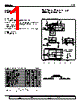
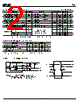


1. Device Overview & Key Parameters
️· Device: IS457 (likely a light sensor or phototransistor).
️· Supply Voltage (Vcc): 4.5V to 5.5V (typical/recommended range)
️· Operating Temperature (Topr): 0°C to 60°C
️· Gain Resistance (Ro): Ranges from 0.39kΩ to 5.1kΩ
️· Incident Light Intensity (Pi): Up to 2.5 (units not specified, but likely Lux or some similar illuminance unit)
2. Performance Characteristics (Derived from Graphs/Tables)
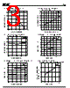
️· Power Dissipation: Graph 1 shows total power dissipation vs. ambient temperature.
️· Low-Level Output Voltage: Figures 3 & 4 show how output voltage varies with temperature and current. It appears to be around 0.2-0.7V depending on conditions.
️· Supply Current (Icc):
- Figure 5 displays how supply current changes with temperature. It’s roughly between 6-8mA.
- Figure 6 shows supply current vs. supply voltage (with two lines, IccL and IccH).
️· Threshold Incident Light Intensity: Figure 7 shows how the threshold light intensity needed to trigger a response changes with supply voltage.
️· Propagation Delay Time: Figure 8 shows delay time versus temperature.
️· Rise/Fall Time: Figure 9 displays the rise and fall time of the device.
3. Spectral Sensitivity
️· Peak Sensitivity: The device is most sensitive to light around 550-600nm (green/yellow wavelengths).
️· Responsiveness: It is less sensitive to blue and red wavelengths.
4. Important Considerations/Precautions (from last line)
️· A section of the datasheet (pages 78-93) covers precautions for use. This is important for proper and safe operation of the device.
5. Test Circuit
️· A test circuit is described in the text. It utilizes a 0.1µF bypass capacitor.
Important Notes & Limitations:
️· Units: Several parameters lack specified units (e.g., incident light intensity). This makes it difficult to interpret some values precisely.
️· Visual Format: The data is presented in a manner that is difficult to parse due to the nested tables and what appears to be PDF rendering artifacts. A more structured table format would be much easier to read.
️· Completeness: This summary is based *only* on the provided text and the labels on the graphs/tables. There is likely more information in the full datasheet (pages 78-93) that is not presented here.
1. Device Overview & Key Parameters
️· Device: IS457 (likely a light sensor or phototransistor).
️· Supply Voltage (Vcc): 4.5V to 5.5V (typical/recommended range)
️· Operating Temperature (Topr): 0°C to 60°C
️· Gain Resistance (Ro): Ranges from 0.39kΩ to 5.1kΩ
️· Incident Light Intensity (Pi): Up to 2.5 (units not specified, but likely Lux or some similar illuminance unit)
2. Performance Characteristics (Derived from Graphs/Tables)
️· Power Dissipation: Graph 1 shows total power dissipation vs. ambient temperature.
️· Low-Level Output Voltage: Figures 3 & 4 show how output voltage varies with temperature and current. It appears to be around 0.2-0.7V depending on conditions.
️· Supply Current (Icc):
- Figure 5 displays how supply current changes with temperature. It’s roughly between 6-8mA.
- Figure 6 shows supply current vs. supply voltage (with two lines, IccL and IccH).
️· Threshold Incident Light Intensity: Figure 7 shows how the threshold light intensity needed to trigger a response changes with supply voltage.
️· Propagation Delay Time: Figure 8 shows delay time versus temperature.
️· Rise/Fall Time: Figure 9 displays the rise and fall time of the device.
3. Spectral Sensitivity
️· Peak Sensitivity: The device is most sensitive to light around 550-600nm (green/yellow wavelengths).
️· Responsiveness: It is less sensitive to blue and red wavelengths.
4. Important Considerations/Precautions (from last line)
️· A section of the datasheet (pages 78-93) covers precautions for use. This is important for proper and safe operation of the device.
5. Test Circuit
️· A test circuit is described in the text. It utilizes a 0.1µF bypass capacitor.
Important Notes & Limitations:
️· Units: Several parameters lack specified units (e.g., incident light intensity). This makes it difficult to interpret some values precisely.
️· Visual Format: The data is presented in a manner that is difficult to parse due to the nested tables and what appears to be PDF rendering artifacts. A more structured table format would be much easier to read.
️· Completeness: This summary is based *only* on the provided text and the labels on the graphs/tables. There is likely more information in the full datasheet (pages 78-93) that is not presented here.
| Part No. | IS457 |
| Manufacturer | SHARP |
| Size | 47 Kbytes |
| Pages | 4 pages |
| Description | High Speed Response Type OPIC Light Detector |
| ALLDATASHEET 가 귀하에 도움이 되셨나요? [ DONATE ] |
Alldatasheet는? | 광고문의 | 운영자에게 연락하기 | 개인정보취급방침 | 링크 투 데이터시트 | 링크교환 | 제조사별 검색 All Rights Reserved©Alldatasheet.com |
| Russian : Alldatasheetru.com | Korean : Alldatasheet.co.kr | Spanish : Alldatasheet.es | French : Alldatasheet.fr | Italian : Alldatasheetit.com Portuguese : Alldatasheetpt.com | Polish : Alldatasheet.pl | Vietnamese : Alldatasheet.vn Indian : Alldatasheet.in | Mexican : Alldatasheet.com.mx | British : Alldatasheet.co.uk | New Zealand : Alldatasheet.co.nz |
|
Family Site : ic2ic.com |
icmetro.com |
 Korean ▼
  English
 Chinese
 German
 Japanese
 Russian
 Spanish
 French
 Italian
 Portuguese
 Polish
 Vietnamese
 Indian
 Mexican
 British
 New Zealand