 |
전자부품 데이터시트 검색엔진 |
|
|
전자부품 데이터시트 검색엔진 |
|
The question interval is too short.
Please try again in a few seconds.

Hello, Please ask a question about COP888CG Datasheet
# Example questions:
➢ Compare the typical supply current (at 6.0v vcc and 1 µs instruction cycle time) for the 88xcg/88xcs/88xeg and 88xcg/88xcs/88xeg. what is the difference?
➢ What is the minimum input setup time for the datasheets (at 5v vcc)?
➢ What is the maximum allowable sink current for the d outputs?
| Part No. | COP888CG |
| Manufacturer | NSC |
| Size | 598 Kbytes |
| Pages | 53 pages |
| Description | 8-Bit CMOS ROM Based Microcontrollers with 4k to 24k Memory, Comparators and USART |













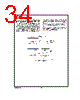


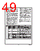


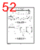


Overall Context:
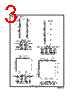
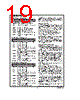
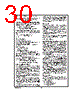
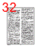
️· These documents describe the electrical characteristics of National Semiconductor (now part of Texas Instruments) microcontrollers. Specifically, there are two series being described: 88xCG, 88xCS, and 88xEG, and 88xCG, 88xCS, and 88xEG
️· These controllers are used in embedded systems where precise timing and reliable data transfer are critical (e.g., industrial control, communication interfaces).
️· The first set of datasheet describes a higher voltage range and slightly different timing values, along with temperature range.
1. Operating Voltage & Power Consumption:
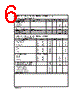
️· Voltage Range: Both series have a similar voltage range, generally from 2.5V to 6.0V. Lower voltage operation reduces power consumption but may impact performance.
️· Supply Current (Icc): This is the amount of current the microcontroller draws from the power supply.
- Active Mode: The microcontroller is actively executing code. Typical values are around 5.5mA to 12.5mA depending on clock speed (CKI) and operating voltage.
- Halt Mode: The microcontroller is in a low-power state, minimal power consumption (around 0.5µA to 2µA, but it depends on the exact implementation).
️· Power Ripple: The microcontroller is sensitive to power supply noise and voltage fluctuations. The maximum allowable voltage ripple is specified as 0.1V.
2. Timing Characteristics (Critical for System Design):
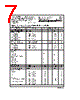
️· Instruction Cycle Time (Tcy): The fundamental clock frequency that governs all operations.
- *Crystal Oscillator:* Tcy is determined by the external crystal frequency.
- *RC Oscillator:* Tcy is determined by the external resistor and capacitor values.
- *Ranges:* The values for Tcy depend on voltage and oscillator type.
️· Setup and Hold Times (Tsu, Thd): These are *absolutely critical* for reliable data transfer.
- *Setup Time:* The amount of time the data signal must be stable *before* the rising edge of the clock signal.
- *Hold Time:* The amount of time the data signal must remain stable *after* the rising edge of the clock signal. If these timing requirements aren't met, data corruption can occur. The 88xCG, 88xCS, and 88xEG has a larger timing values, which might influence decisions.
️· Output Propagation Delay (TPD): The time it takes for an output signal to change after the corresponding internal signal changes.
3. Input/Output (I/O) Characteristics:
️· Drive Strength: The microcontroller's ability to drive external loads (e.g., LEDs, other devices). The datasheet will specify the output voltage levels for different load conditions.
️· Input Leakage Current: Small current that flows into the microcontroller's input pins when they are not actively driven.
4. Special Interface – MICROWIRE:
️· MICROWIRE is a serial communication protocol used by these microcontrollers.
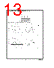
️· T<sub>UWS</sub> (Setup Time): Data must be stable *before* the MICROWIRE clock signal rises.
️· T<sub>UWH</sub> (Hold Time): Data must remain stable *after* the MICROWIRE clock signal rises.
️· T<sub>UPD</sub> (Propagation Delay): How long it takes for the output to respond to a MICROWIRE command.
5. Miscellaneous Timing:
️· Reset Pulse Width: Minimum width of the reset signal required to properly reset the microcontroller.
Key Differences between 88xCG, 88xCS, and 88xEG:
️· Voltage and Temperature Range: The 88xCG, 88xCS, and 88xEG is able to operate from a lower voltage and larger temperature range, enabling more deployment options.
Important Notes for Design:
️· Decoupling Capacitors: Always use decoupling capacitors near the microcontroller's power pins to filter noise and ensure stable power supply.
️· Crystal Selection: If using a crystal oscillator, select a crystal that meets the microcontroller's specified frequency and load capacitance requirements.
️· Board Layout: Pay close attention to board layout to minimize signal path lengths, reduce noise, and ensure proper impedance matching.
Overall Context:
️· These documents describe the electrical characteristics of National Semiconductor (now part of Texas Instruments) microcontrollers. Specifically, there are two series being described: 88xCG, 88xCS, and 88xEG, and 88xCG, 88xCS, and 88xEG
️· These controllers are used in embedded systems where precise timing and reliable data transfer are critical (e.g., industrial control, communication interfaces).
️· The first set of datasheet describes a higher voltage range and slightly different timing values, along with temperature range.
1. Operating Voltage & Power Consumption:
️· Voltage Range: Both series have a similar voltage range, generally from 2.5V to 6.0V. Lower voltage operation reduces power consumption but may impact performance.
️· Supply Current (Icc): This is the amount of current the microcontroller draws from the power supply.
- Active Mode: The microcontroller is actively executing code. Typical values are around 5.5mA to 12.5mA depending on clock speed (CKI) and operating voltage.
- Halt Mode: The microcontroller is in a low-power state, minimal power consumption (around 0.5µA to 2µA, but it depends on the exact implementation).
️· Power Ripple: The microcontroller is sensitive to power supply noise and voltage fluctuations. The maximum allowable voltage ripple is specified as 0.1V.
2. Timing Characteristics (Critical for System Design):
️· Instruction Cycle Time (Tcy): The fundamental clock frequency that governs all operations.
- *Crystal Oscillator:* Tcy is determined by the external crystal frequency.
- *RC Oscillator:* Tcy is determined by the external resistor and capacitor values.
- *Ranges:* The values for Tcy depend on voltage and oscillator type.
️· Setup and Hold Times (Tsu, Thd): These are *absolutely critical* for reliable data transfer.
- *Setup Time:* The amount of time the data signal must be stable *before* the rising edge of the clock signal.
- *Hold Time:* The amount of time the data signal must remain stable *after* the rising edge of the clock signal. If these timing requirements aren't met, data corruption can occur. The 88xCG, 88xCS, and 88xEG has a larger timing values, which might influence decisions.
️· Output Propagation Delay (TPD): The time it takes for an output signal to change after the corresponding internal signal changes.
3. Input/Output (I/O) Characteristics:
️· Drive Strength: The microcontroller's ability to drive external loads (e.g., LEDs, other devices). The datasheet will specify the output voltage levels for different load conditions.
️· Input Leakage Current: Small current that flows into the microcontroller's input pins when they are not actively driven.
4. Special Interface – MICROWIRE:
️· MICROWIRE is a serial communication protocol used by these microcontrollers.
️· T<sub>UWS</sub> (Setup Time): Data must be stable *before* the MICROWIRE clock signal rises.
️· T<sub>UWH</sub> (Hold Time): Data must remain stable *after* the MICROWIRE clock signal rises.
️· T<sub>UPD</sub> (Propagation Delay): How long it takes for the output to respond to a MICROWIRE command.
5. Miscellaneous Timing:
️· Reset Pulse Width: Minimum width of the reset signal required to properly reset the microcontroller.
Key Differences between 88xCG, 88xCS, and 88xEG:
️· Voltage and Temperature Range: The 88xCG, 88xCS, and 88xEG is able to operate from a lower voltage and larger temperature range, enabling more deployment options.
Important Notes for Design:
️· Decoupling Capacitors: Always use decoupling capacitors near the microcontroller's power pins to filter noise and ensure stable power supply.
️· Crystal Selection: If using a crystal oscillator, select a crystal that meets the microcontroller's specified frequency and load capacitance requirements.
️· Board Layout: Pay close attention to board layout to minimize signal path lengths, reduce noise, and ensure proper impedance matching.
| Part No. | COP888CG |
| Manufacturer | NSC |
| Size | 598 Kbytes |
| Pages | 53 pages |
| Description | 8-Bit CMOS ROM Based Microcontrollers with 4k to 24k Memory, Comparators and USART |
| ALLDATASHEET 가 귀하에 도움이 되셨나요? [ DONATE ] |
Alldatasheet는? | 광고문의 | 운영자에게 연락하기 | 개인정보취급방침 | 링크 투 데이터시트 | 링크교환 | 제조사별 검색 All Rights Reserved©Alldatasheet.com |
| Russian : Alldatasheetru.com | Korean : Alldatasheet.co.kr | Spanish : Alldatasheet.es | French : Alldatasheet.fr | Italian : Alldatasheetit.com Portuguese : Alldatasheetpt.com | Polish : Alldatasheet.pl | Vietnamese : Alldatasheet.vn Indian : Alldatasheet.in | Mexican : Alldatasheet.com.mx | British : Alldatasheet.co.uk | New Zealand : Alldatasheet.co.nz |
|
Family Site : ic2ic.com |
icmetro.com |
 Korean ▼
  English
 Chinese
 German
 Japanese
 Russian
 Spanish
 French
 Italian
 Portuguese
 Polish
 Vietnamese
 Indian
 Mexican
 British
 New Zealand