|
전자부품 데이터시트 검색엔진 |
|
|
전자부품 데이터시트 검색엔진 |
|
FT6264L-25LSMLF 데이터시트(PDF) 7 Page - Force Technologies Ltd |
|
|
|||||||||||||||||||||||||||||
FT6264L-25LSMLF 데이터시트(HTML) 7 Page - Force Technologies Ltd |
|
|
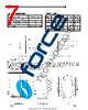
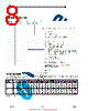
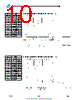
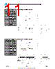
7 / 17 page  Mode CE CE CE CE CE 1 CE 2 OE OE OE OE OE WE WE WE WE WE I/O Power Standby H X X X High Z Standby Standby X L X X High Z Standby D OUT Disabled L H H H High Z Active Read L H L H D OUT Active Write L H X L High Z Active AC TEST CONDITIONS Input Pulse Levels GND to 3.0V Input Rise and Fall Times 3ns Input Timing Reference Level 1.5V Output Timing Reference Level 1.5V Output Load See Figures 1 and 2 TRUTH TABLE Figure 1. Output Load Figure 2. Thevenin Equivalent * including scope and test fixture. Note: Because of the high speed of the FT6264/L, care must be taken when testing this device; an inadequate setup can cause a normal functioning part to be rejected as faulty. Long high-inductance leads that cause supply bounce must be avoided by bringing the V CC and ground planes directly up to the contactor fingers. A 0.01 µF high frequency capacitor is also required between V CC and ground. To avoid signal reflections, proper termination must be used; for example, a 50Ω test environment should be terminated into a 50Ω load with 1.73V (Thevenin Voltage) at the comparator input, and a 116Ω resistor must be used in series with D OUT to match 166 Ω (Thevenin Resistance). LCC (L5) "LS" - SPECIAL PIN-OUT LCC PIN CONFIGURATIONS LCC (L6) LCC (L5) "L" - STANDARD PIN-OUT Rev 1.8 7/17 2012 |
|
|
링크 URL |
| ALLDATASHEET 가 귀하에 도움이 되셨나요? [ DONATE ] |
Alldatasheet는? | 광고문의 | 운영자에게 연락하기 | 개인정보취급방침 | 링크 투 데이터시트 | 링크교환 | 제조사별 검색 All Rights Reserved©Alldatasheet.com |
| Russian : Alldatasheetru.com | Korean : Alldatasheet.co.kr | Spanish : Alldatasheet.es | French : Alldatasheet.fr | Italian : Alldatasheetit.com Portuguese : Alldatasheetpt.com | Polish : Alldatasheet.pl | Vietnamese : Alldatasheet.vn Indian : Alldatasheet.in | Mexican : Alldatasheet.com.mx | British : Alldatasheet.co.uk | New Zealand : Alldatasheet.co.nz |
|
Family Site : ic2ic.com |
icmetro.com |
 Korean ▼
 English
 Chinese
 German
 Japanese
 Russian
 Korean
 Spanish
 French
 Italian
 Portuguese
 Polish
 Vietnamese
 Indian
 Mexican
 British
 New Zealand