|
전자부품 데이터시트 검색엔진 |
|
|
전자부품 데이터시트 검색엔진 |
|
M8870-R3 데이터시트(PDF) 3 Page - Clare, Inc. |
|
|
|||||||||||||||||||||||||||||
M8870-R3 데이터시트(HTML) 3 Page - Clare, Inc. |
|
|
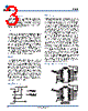
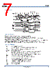
3 / 9 page  M-8870 www.clare.com 3 Rev. 3 Basic Steering Circuit Single-Ended Input Configuration Functional Description M-8870 operating functions (see block diagram on page 1) include a bandsplit filter that separates the high and low tones of the received pair, and a digital decoder that verifies both the frequency and duration of the received tones before passing the resulting 4-bit code to the output bus. Filter The low and high group tones are separated by apply- ing the dual-tone signal to the inputs of two 6th order switched capacitor bandpass filters with bandwidths that correspond to the bands enclosing the low and high group tones. The filter also incorporates notches at 350 and 440 Hz, providing excellent dial tone rejec- tion. Each filter output is followed by a single-order switched capacitor section that smooths the signals prior to limiting. Signal limiting is performed by high- gain comparators provided with hysteresis to prevent detection of unwanted low-level signals and noise. The comparator outputs provide full-rail logic swings at the frequencies of the incoming tones. Decoder The M-8870 decoder uses a digital counting tech- nique to determine the frequencies of the limited tones and to verify that they correspond to standard DTMF frequencies. A complex averaging algorithm is used to protect against tone simulation by extraneous signals (such as voice) while tolerating small frequency varia- tions. The algorithm ensures an optimum combination of immunity to talkoff and tolerance to interfering sig- nals (third tones) and noise. When the detector rec- ognizes the simultaneous presence of two valid tones (known as signal condition), it raises the Early Steering flag (ESt). Any subsequent loss of signal condition will cause ESt to fall. Steering Circuit Before a decoded tone pair is registered, the receiver checks for a valid signal duration (referred to as char- acter-recognition-condition). This check is performed by an external RC time constant driven by ESt. A logic high on ESt causes VC (see block diagram on page 1) to rise as the capacitor discharges. Provided that sig- nal condition is maintained (ESt remains high) for the validation period (t GTF), VC reaches the threshold (VTSt) of the steering logic to register the tone pair, thus latch- ing its corresponding 4-bit code (see DC Characteristics on page 2) into the output latch. At this point, the GT output is activated and drives V C to VDD. GT continues to drive high as long as ESt remains high. Finally, after a short delay to allow the output latch to settle, the delayed steering output flag (StD) goes high, signaling that a received tone pair has been registered. The contents of the output latch are made available on the 4-bit output bus by raising the three- state control input (OE) to a logic high. The steering circuit works in reverse to validate the interdigit pause between signals. Thus, as well as rejecting signals too short to be considered valid, the receiver will tolerate signal interruptions (dropouts) too short to be consid- ered a valid pause. This capability, together with the ability to select the steering time constants externally, allows the designer to tailor performance to meet a wide variety of system requirements. |
|
|
링크 URL |
| ALLDATASHEET 가 귀하에 도움이 되셨나요? [ DONATE ] |
Alldatasheet는? | 광고문의 | 운영자에게 연락하기 | 개인정보취급방침 | 링크 투 데이터시트 | 링크교환 | 제조사별 검색 All Rights Reserved©Alldatasheet.com |
| Russian : Alldatasheetru.com | Korean : Alldatasheet.co.kr | Spanish : Alldatasheet.es | French : Alldatasheet.fr | Italian : Alldatasheetit.com Portuguese : Alldatasheetpt.com | Polish : Alldatasheet.pl | Vietnamese : Alldatasheet.vn Indian : Alldatasheet.in | Mexican : Alldatasheet.com.mx | British : Alldatasheet.co.uk | New Zealand : Alldatasheet.co.nz |
|
Family Site : ic2ic.com |
icmetro.com |
 Korean ▼
 English
 Chinese
 German
 Japanese
 Russian
 Korean
 Spanish
 French
 Italian
 Portuguese
 Polish
 Vietnamese
 Indian
 Mexican
 British
 New Zealand