|
전자부품 데이터시트 검색엔진 |
|
|
전자부품 데이터시트 검색엔진 |
|
LM393DGKRG4 데이터시트(PDF) 23 Page - Texas Instruments |
|
|
|
|||||||||||||||||||||||||||||
LM393DGKRG4 데이터시트(HTML) 23 Page - Texas Instruments |
|
|
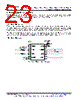
23 / 46 page  VCC Ground 6 5 7 1 2 3 4 8 Ground PF 1IN- 1IN+ GND 2OUT 2IN- 2IN+ 1OUT VCC OK VCC or GND Better Input Resistors Close to device 23 LM193, LM293, LM293A, LM393, LM393A, LM2903, LM2903V, LM393B, LM2903B www.ti.com SLCS005AB – OCTOBER 1979 – REVISED DECEMBER 2019 Product Folder Links: LM193 LM293 LM293A LM393 LM393A LM2903 LM2903V LM393B LM2903B Submit Documentation Feedback Copyright © 1979–2019, Texas Instruments Incorporated 9 Power Supply Recommendations For fast response and comparison applications with noisy or AC inputs, TI recommends to use a bypass capacitor on the supply pin to reject any variation on the supply voltage. This variation can eat into the input common-mode range of the comparator and create an inaccurate comparison. 10 Layout 10.1 Layout Guidelines For accurate comparator applications without hysteresis it is important maintain a stable power supply with minimized noise and glitches. To achieve this, it is best to add a bypass capacitor between the supply voltage and ground. This should be implemented on the positive power supply and negative supply (if available). If a negative supply is not being used, do not put a capacitor between the IC's GND pin and system ground. Minimize coupling between outputs and inverting inputs to prevent output oscillations. Do not run output and inverting input traces in parallel unless there is a VCC or GND trace between output and inverting input traces to reduce coupling. When series resistance is added to inputs, place resistor close to the device. 10.2 Layout Example Figure 42. LM2903 Layout Example |
|
링크 URL |
| ALLDATASHEET 가 귀하에 도움이 되셨나요? [ DONATE ] |
Alldatasheet는? | 광고문의 | 운영자에게 연락하기 | 개인정보취급방침 | 링크 투 데이터시트 | 링크교환 | 제조사별 검색 All Rights Reserved©Alldatasheet.com |
| Russian : Alldatasheetru.com | Korean : Alldatasheet.co.kr | Spanish : Alldatasheet.es | French : Alldatasheet.fr | Italian : Alldatasheetit.com Portuguese : Alldatasheetpt.com | Polish : Alldatasheet.pl | Vietnamese : Alldatasheet.vn Indian : Alldatasheet.in | Mexican : Alldatasheet.com.mx | British : Alldatasheet.co.uk | New Zealand : Alldatasheet.co.nz |
|
Family Site : ic2ic.com |
icmetro.com |
 Korean ▼
 English
 Chinese
 German
 Japanese
 Russian
 Korean
 Spanish
 French
 Italian
 Portuguese
 Polish
 Vietnamese
 Indian
 Mexican
 British
 New Zealand