|
전자부품 데이터시트 검색엔진 |
|
|
전자부품 데이터시트 검색엔진 |
|
M2MNV-22-R 데이터시트(PDF) 5 Page - M-System Co.,Ltd. |
|
|
|||||||||||||||||||||||||||||
M2MNV-22-R 데이터시트(HTML) 5 Page - M-System Co.,Ltd. |
|
|
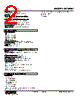
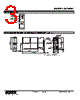
5 / 6 page  MODEL: M2MNV M2MNV SPECIFICATIONS ES-5095 Rev.9 Page 5/6 http://www.m-system.co.jp/ SWITCHING OPERATIONS 1 2 4 5 7 8 1 2 4 5 7 8 Current Signal (no receiving resistor) Power : OFF Switching command : OFF (open) 1 2 4 5 7 8 1 2 4 5 7 8 Power : ON Switching command : OFF (open) 1 2 4 5 7 8 1 2 4 5 7 8 Power : ON Switching command : ON (short) Current Signal (receiving resistor 50 Ω) Voltage Signal Current Signal (no receiving resistor) Transition (ON to OFF, OFF to ON) Status Power : ON Switching command : OFF to ON or Power : ON Switching command : ON to OFF Current Signal (receiving resistor 50 Ω) Voltage Signal *1. Resistor is provided only for the input code 2: Current signal (receiving resistor 50 Ω). *1. Resistor is provided only for the input code 2: Current signal (receiving resistor 50 Ω). *1 *1 *1 *1 1 2 4 5 7 8 1 2 4 5 7 8 *1 *1 *1 *1 • Switching Status When the switching command contact is switched from OFF to ON or from ON to OFF, the signal channel is switched only after all photo MOSFET relays turn on (closed). When the switching command contact is switched from OFF to ON or from ON to OFF, the signal channel is switched only after all photo MOSFET relays turn off (open). ■ INTERLOCKING SWITCHING CONTROL (single-pole contact) Single contact is used to switch from Signal Channel 1 (A1 – B1) to Signal Channel 2 (A2 – B1) and vice versa. CHANNEL 1 (A1) CHANNEL 2 (A2) Terminal 3 – 9 OFF (open) OFF ON Terminal 3 – 9 ON (closed) ON OFF Status LED turn on when the respective channels are alive. ■ INDEPENDENT SWITCHING CONTROL (double-pole contact) Double contacts are used to independently switch Signal Channel 1 (A1 – B1) and Signal Channel 2 (A2 – B1). CHANNEL 1 (A1) CHANNEL 2 (A2) Terminal 3 – 9 OFF (open) OFF ---- Terminal 3 – 9 ON (closed) ON ---- Terminal 6 – 9 OFF (open) ---- OFF Terminal 6 – 9 ON (closed) ---- ON Status LED turn on when the respective channels are alive. |
|
|
링크 URL |
| ALLDATASHEET 가 귀하에 도움이 되셨나요? [ DONATE ] |
Alldatasheet는? | 광고문의 | 운영자에게 연락하기 | 개인정보취급방침 | 링크 투 데이터시트 | 링크교환 | 제조사별 검색 All Rights Reserved©Alldatasheet.com |
| Russian : Alldatasheetru.com | Korean : Alldatasheet.co.kr | Spanish : Alldatasheet.es | French : Alldatasheet.fr | Italian : Alldatasheetit.com Portuguese : Alldatasheetpt.com | Polish : Alldatasheet.pl | Vietnamese : Alldatasheet.vn Indian : Alldatasheet.in | Mexican : Alldatasheet.com.mx | British : Alldatasheet.co.uk | New Zealand : Alldatasheet.co.nz |
|
Family Site : ic2ic.com |
icmetro.com |
 Korean ▼
 English
 Chinese
 German
 Japanese
 Russian
 Korean
 Spanish
 French
 Italian
 Portuguese
 Polish
 Vietnamese
 Indian
 Mexican
 British
 New Zealand