|
전자부품 데이터시트 검색엔진 |
|
|
전자부품 데이터시트 검색엔진 |
|
FU008-A-R-SD 데이터시트(PDF) 17 Page - ABLIC Inc. |
|
|
|||||||||||||||||||||||||||||
FU008-A-R-SD 데이터시트(HTML) 17 Page - ABLIC Inc. |
|
|
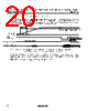
17 / 29 page  CONVENIENCE TIMER AUTOMOTIVE, 125°C OPERATION, 2-WIRE TIMER WITH BUILT-IN QUARTZ CRYSTAL Rev.2.1_00 S-35710M A Series 17 7. Read operation of wake-up time register Perform the read operation of the wake-up time register with the restart format. Regarding the restart format, refer to "4. Data transmission format". When performing the read operation of the wake-up time register, set the RST _______ pin to "H". If the RST _______ pin is set to "L", the time register data is read. Transmit the start condition and the slave address from the master device. The slave address of the S-35710M is specified to "0110010". Next, transmit "0" to the read / write bit. B7 in the 2nd byte is an address pointer. Set B7 to "0" when reading the wake-up time register. Next, transmit the dummy data to B6 to B1. Make sure to set B0 to "1" since it is a test bit. This processing is called "dummy write". Then transmit the start condition, the slave address and the read / write bit. The data of the wake-up time register can be read when the read / write bit is set to "1". Consequently, the data of the wake-up time register is output from the S-35710M. Each byte from B7 is transmitted. When the read operation of the wake-up time register is finished, transmit "1" (NO_ACK) to the acknowledge after B0 output from the master device, and then transmit the stop condition. The wake-up time register is a 3-byte register. "1" is read if the read operation is performed continuously after reading 3 bytes of the wake-up time register. Regarding the wake-up time register, refer to " Configuration of Registers". Moreover, the internal address pointer is reset if recognizing the stop condition. Therefore, do not transmit the stop condition after dummy write operation. The time register is read if performing the read operation of the register after transmitting the stop condition. 19 18 1 9 18 27 36 SCL 1 0 1 0 0 1 1 0 B1 B7 B0 B7 B0 B7 B0 B7 SDA Wake-up time register (3-byte) 0 B0 B7 Dummy data *1 Dummy write Slave address (0110010) 1 0 1 0 0 1 1 0 B1R/W 0 R/W B7 Slave address (0110010) Make sure to set B0 to "1" since it is a test bit. Input NO_ACK after the 3rd byte transmission. Set B7 as an address pointer. *1. Set B6 to B1 to "0" or "1" since they are dummy data. : S-35710M output data : Master device input data Figure 20 Read Timing of Wake-up Time Register |
|
|
링크 URL |
| ALLDATASHEET 가 귀하에 도움이 되셨나요? [ DONATE ] |
Alldatasheet는? | 광고문의 | 운영자에게 연락하기 | 개인정보취급방침 | 링크 투 데이터시트 | 링크교환 | 제조사별 검색 All Rights Reserved©Alldatasheet.com |
| Russian : Alldatasheetru.com | Korean : Alldatasheet.co.kr | Spanish : Alldatasheet.es | French : Alldatasheet.fr | Italian : Alldatasheetit.com Portuguese : Alldatasheetpt.com | Polish : Alldatasheet.pl | Vietnamese : Alldatasheet.vn Indian : Alldatasheet.in | Mexican : Alldatasheet.com.mx | British : Alldatasheet.co.uk | New Zealand : Alldatasheet.co.nz |
|
Family Site : ic2ic.com |
icmetro.com |
 Korean ▼
 English
 Chinese
 German
 Japanese
 Russian
 Korean
 Spanish
 French
 Italian
 Portuguese
 Polish
 Vietnamese
 Indian
 Mexican
 British
 New Zealand