|
전자부품 데이터시트 검색엔진 |
|
|
전자부품 데이터시트 검색엔진 |
|
BAV20WS-TP 데이터시트(PDF) 25 Page - Infineon Technologies AG |
|
|
|||||||||||||||||||||||||||||
BAV20WS-TP 데이터시트(HTML) 25 Page - Infineon Technologies AG |
|
|
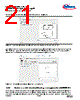
25 / 47 page  User Manual 25 of 47 Revision 1.4 2020-07-16 EVAL-M3-IM564 User Manual iMOTION™ Modular Application Design Kit Hardware description of EVAL-M3-IM564 4.2.1 DC bus sensing and MCEWizard configuration Pin 14 and pin 26 of connector J3 provide access to the DC-link voltage DCBsense. Three possible feedback cases are associated with these pins. Figure 19 provides the DC bus sense resistor details. By default, the resistor R21 is not mounted on EVAL-M3-IM564. A pull-down resistor must be mounted on the corresponding controller board. Figure 19 DC bus sense resistor on EVAL-M3-IM564 evaluation board If a pull-down resistor of 13.3 kΩ referred to ground is inserted either on the EVAL-M3-IM564 evaluation board or on the control board, the DCBSense voltage results in the range of 0 to 3.3 V on the pin reflecting a DC bus voltage range of 0 to 420 V. If a pull-down resistor of 13.3 kΩ is inserted on both the EVAL-M3-IM564 evaluation board and on the control card, the DCBSense results scale to 0-1.65 V. No safety issue occurs. If no feedback is desired on the DCBSense pin, R6 or R14 should be removed to avoid high voltage on the connector. The high-side resistors R6 and R14 for the DC bus sensing resistor divider on the controller board EVAL-M3- IM564 are 2000 kΩ, and should be configured in MCEWizard as shown in Figure 20. For the low-side resistor value, please refer to the User Manual of the corresponding control board (typical is 13.3 kΩ). Figure 20 DC bus sensing configuration in MCEWizard DCBsense R14 1.00M, 1% R6 1.00M, 1% R21 DNI DCBSense DCBUS |
|
링크 URL |
| ALLDATASHEET 가 귀하에 도움이 되셨나요? [ DONATE ] |
Alldatasheet는? | 광고문의 | 운영자에게 연락하기 | 개인정보취급방침 | 링크 투 데이터시트 | 링크교환 | 제조사별 검색 All Rights Reserved©Alldatasheet.com |
| Russian : Alldatasheetru.com | Korean : Alldatasheet.co.kr | Spanish : Alldatasheet.es | French : Alldatasheet.fr | Italian : Alldatasheetit.com Portuguese : Alldatasheetpt.com | Polish : Alldatasheet.pl | Vietnamese : Alldatasheet.vn Indian : Alldatasheet.in | Mexican : Alldatasheet.com.mx | British : Alldatasheet.co.uk | New Zealand : Alldatasheet.co.nz |
|
Family Site : ic2ic.com |
icmetro.com |
 Korean ▼
 English
 Chinese
 German
 Japanese
 Russian
 Korean
 Spanish
 French
 Italian
 Portuguese
 Polish
 Vietnamese
 Indian
 Mexican
 British
 New Zealand