|
전자부품 데이터시트 검색엔진 |
|
|
전자부품 데이터시트 검색엔진 |
|
AT45DB321C-RU 데이터시트(PDF) 9 Page - ATMEL Corporation |
|
|
|||||||||||||||||||||||||||||
AT45DB321C-RU 데이터시트(HTML) 9 Page - ATMEL Corporation |
|
|
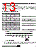
9 / 40 page  9 3387L–DFLASH–6/06 AT45DB321C Main Memory Page Program without Built-in Erase, Page Erase, Block Erase, Main Memory Page Program, and Auto Page Rewrite. Bit 1 in the Status Register is used to provide information to the user whether or not the sector protection has been enabled or disabled, either by software-controlled method or hardware-con- trolled method. A logic 1 indicates that sector protection has been enabled and logic 0 indicates that sector protection has been disabled. The device density is indicated using bits 5, 4, 3, and 2 of the status register. For the AT45DB321C, the four bits are 1,1, 0, 1. The decimal value of these four binary bits does not equate to the device density; the four bits represent a combinational code relating to differing densities of DataFlash devices. The device density is not the same as the density code indicated in the JEDEC device ID information. The device density is provided only for backward compatibility. The result of the most recent Main Memory Page to Buffer Compare operation is indicated using bit 6 of the status register. If bit 6 is a 0, then the data in the main memory page matches the data in the buffer. If bit 6 is a 1, then at least one bit of the data in the main memory page does not match the data in the buffer. 6. Sector Protection Two protection methods, hardware and software controlled, are provided. The selection of which sectors to be protected/unprotected from program and erase operations is defined in the Sector Protection Register. 6.1 Software Sector Protection Sectors specified for protection in the Sector Protection Register can be protected from program and erase operations by issuing the Enable Sector Protection command. To enable the sector protection using the software controlled method, the CS pin must first be asserted as it would be with any other command. Once the CS pin has been asserted, the appropriate 4-byte command sequence must be clocked in via the input pin (SI). After the last bit of the command sequence has been clocked in, the CS pin must be deasserted after which the sector protection will be enabled. To disable the sector protection using the software controlled method, the CS pin must first be asserted as it would be with any other command. Once the CS pin has been asserted, the appropriate 4-byte sequence for the Disable Sector Protection command must be clocked in via the input pin (SI). After the last bit of the command sequence has been clocked in, the CS pin must be deasserted after which the sector protection will be disabled. The Disable Sector Pro- tection command is ignored while the WP pin is asserted. Table 5-2. Status Register Format Bit 7 Bit 6 Bit 5 Bit 4 Bit 3 Bit 2 Bit 1 Bit 0 RDY/BUSY COMP 1 1 0 1 Protect X Command Byte 1 Byte 2 Byte 3 Byte 4 Enable Sector Protection 3DH 2AH 7FH A9H Disable Sector Protection 3DH 2AH 7FH 9AH Read Sector Protection Register 32H 00H 00H 00H |
|
링크 URL |
| ALLDATASHEET 가 귀하에 도움이 되셨나요? [ DONATE ] |
Alldatasheet는? | 광고문의 | 운영자에게 연락하기 | 개인정보취급방침 | 링크 투 데이터시트 | 링크교환 | 제조사별 검색 All Rights Reserved©Alldatasheet.com |
| Russian : Alldatasheetru.com | Korean : Alldatasheet.co.kr | Spanish : Alldatasheet.es | French : Alldatasheet.fr | Italian : Alldatasheetit.com Portuguese : Alldatasheetpt.com | Polish : Alldatasheet.pl | Vietnamese : Alldatasheet.vn Indian : Alldatasheet.in | Mexican : Alldatasheet.com.mx | British : Alldatasheet.co.uk | New Zealand : Alldatasheet.co.nz |
|
Family Site : ic2ic.com |
icmetro.com |
 Korean ▼
 English
 Chinese
 German
 Japanese
 Russian
 Korean
 Spanish
 French
 Italian
 Portuguese
 Polish
 Vietnamese
 Indian
 Mexican
 British
 New Zealand