|
전자부품 데이터시트 검색엔진 |
|
|
전자부품 데이터시트 검색엔진 |
|
USB0408 데이터시트(PDF) 4 Page - Protek Devices |
|
|
|||||||||||||||||||||||||||||
USB0408 데이터시트(HTML) 4 Page - Protek Devices |
|
|
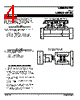
4 / 5 page  USB0403 thru USB0424C 4 05205.R1 6/06 www.protekdevices.com CIRCUIT BOARD LAYOUT RECOMMENDATIONS Circuit board layout is critical for Electromagnetic Compatibility (EMC) protection. The following guidelines are recommended: ✔ The protection device should be placed near the input terminals or connectors, the device will divert the transient current immediately before it can be coupled into the nearby traces. ✔ The path length between the TVS device and the protected line should be minimized. ✔ All conductive loops including power and ground loops should be minimized. ✔ The transient current return path to ground should be kept as short as possible to reduce parasitic inductance. ✔ Ground planes should be used whenever possible. For multilayer PCBs, use ground vias. The USB04 Series are TVS arrays designed to protect I/O or data lines from the damaging effects of ESD and EFT. This product series provides both unidirectional and bidirectional protection, with a surge capability of 500 Watts P PP per line for an 8/20µs waveform and ESD protection > 40kV. UNIDIRECTIONAL COMMON-MODE CONFIGURATION (Figure 1) The two USB04 Series devices provide protection in a common- mode configuration as depicted in Figure 1. Circuit connectivity is as follows: ✔ TVS Device 1: Line 1(D+) is connected to Pins 2 & 3. ✔ TVS Device 2: Line 2(D-) is connected to Pins 2 & 3. ✔ Both TVS Devices: Pins 1 & 4 connected to ground. BIDIRECTIONAL DIFFERENTIAL-MODE CONFIGURATION (Figure 2) The USB04xxC Series provides protection in a differential-mode configuration as depicted in Figure 2. Circuit connectivity is as follows: ✔ Line 1(R X) is connected to Pins 1 & 4. ✔ Line 2(T X) is connected to Pins 2 & 3. Figure 1 - Unidirectional Configuration (Two TVS Devices) Common-Mode USB Protection ;;;;;;;;;;;;;;;;;;;;;;;;;;;;;;;;;;;;;;;;;;;;;; ;;;;;;;;;;;;;;;;;;;;;;;;;;;;;;;;;;;;;;;;;;;;;; ;;;;;;;;;;;;;;;;;;;;;;;;;;;;;;;;;;;;;;;;;;;;;; ;;;;;;;;;;;;;;;;;;;;;;;;;;;;;;;;;;;;;;;;;;;;;; ;;;;;;;;;;;;;;;;;;;;;;;;;;;;;;;;;;;;;;;;;;;;;; ;;;;;;;;;;;;;;;;;;;;;;;;;;;;;;;;;;;;;;;;;;;;;; ;;;;;;;;;;;;;;;;;;;;;;;;;;;;;;;;;;;;;;;;;;;;;; 1 4 3 2 1 4 2 3 D+ USB IC D- GND SOLDER PAD Figure 2 - Bidirectional Configuration Differential-Mode Ethernet Protection 1 4 3 2 R R T X R X APPLICATIONS |
|
|
링크 URL |
| ALLDATASHEET 가 귀하에 도움이 되셨나요? [ DONATE ] |
Alldatasheet는? | 광고문의 | 운영자에게 연락하기 | 개인정보취급방침 | 링크 투 데이터시트 | 링크교환 | 제조사별 검색 All Rights Reserved©Alldatasheet.com |
| Russian : Alldatasheetru.com | Korean : Alldatasheet.co.kr | Spanish : Alldatasheet.es | French : Alldatasheet.fr | Italian : Alldatasheetit.com Portuguese : Alldatasheetpt.com | Polish : Alldatasheet.pl | Vietnamese : Alldatasheet.vn Indian : Alldatasheet.in | Mexican : Alldatasheet.com.mx | British : Alldatasheet.co.uk | New Zealand : Alldatasheet.co.nz |
|
Family Site : ic2ic.com |
icmetro.com |
 Korean ▼
 English
 Chinese
 German
 Japanese
 Russian
 Korean
 Spanish
 French
 Italian
 Portuguese
 Polish
 Vietnamese
 Indian
 Mexican
 British
 New Zealand