|
전자부품 데이터시트 검색엔진 |
|
|
전자부품 데이터시트 검색엔진 |
|
PCF8591 데이터시트(PDF) 6 Page - NXP Semiconductors |
|
|
|||||||||||||||||||||||||||||
PCF8591 데이터시트(HTML) 6 Page - NXP Semiconductors |
|
|
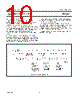
6 / 28 page  1998 Jul 02 6 Philips Semiconductors Product specification 8-bit A/D and D/A converter PCF8591 7 FUNCTIONAL DESCRIPTION 7.1 Addressing Each PCF8591 device in an I2C-bus system is activated by sending a valid address to the device. The address consists of a fixed part and a programmable part. The programmable part must be set according to the address pins A0, A1 and A2. The address always has to be sent as the first byte after the start condition in the I2C-bus protocol. The last bit of the address byte is the read/write-bit which sets the direction of the following data transfer (see Figs 3, 15 and 16). Fig.3 Address byte. 7.2 Control byte The second byte sent to a PCF8591 device will be stored in its control register and is required to control the device function. The upper nibble of the control register is used for enabling the analog output, and for programming the analog inputs as single-ended or differential inputs. The lower nibble selects one of the analog input channels defined by the upper nibble (see Fig.4). If the auto-increment flag is set the channel number is incremented automatically after each A/D conversion. If the auto-increment mode is desired in applications where the internal oscillator is used, the analog output enable flag in the control byte (bit 6) should be set. This allows the internal oscillator to run continuously, thereby preventing conversion errors resulting from oscillator start-up delay. The analog output enable flag may be reset at other times to reduce quiescent power consumption. The selection of a non-existing input channel results in the highest available channel number being allocated. Therefore, if the auto-increment flag is set, the next selected channel will be always channel 0. The most significant bits of both nibbles are reserved for future functions and have to be set to 0. After a Power-on reset condition all bits of the control register are reset to 0. The D/A converter and the oscillator are disabled for power saving. The analog output is switched to a high-impedance state. |
|
|
링크 URL |
| ALLDATASHEET 가 귀하에 도움이 되셨나요? [ DONATE ] |
Alldatasheet는? | 광고문의 | 운영자에게 연락하기 | 개인정보취급방침 | 링크 투 데이터시트 | 링크교환 | 제조사별 검색 All Rights Reserved©Alldatasheet.com |
| Russian : Alldatasheetru.com | Korean : Alldatasheet.co.kr | Spanish : Alldatasheet.es | French : Alldatasheet.fr | Italian : Alldatasheetit.com Portuguese : Alldatasheetpt.com | Polish : Alldatasheet.pl | Vietnamese : Alldatasheet.vn Indian : Alldatasheet.in | Mexican : Alldatasheet.com.mx | British : Alldatasheet.co.uk | New Zealand : Alldatasheet.co.nz |
|
Family Site : ic2ic.com |
icmetro.com |
 Korean ▼
 English
 Chinese
 German
 Japanese
 Russian
 Korean
 Spanish
 French
 Italian
 Portuguese
 Polish
 Vietnamese
 Indian
 Mexican
 British
 New Zealand