전자부품 데이터시트 검색엔진
  Korean  ▼
ALLDATASHEET.CO.KR

X  

IP1001-DS-R05 데이터시트(PDF) 14 Page - List of Unclassifed Manufacturers

부품명 IP1001-DS-R05
상세설명  Integrated 10/100/1000 Gigabit Ethernet Transceiver
PDF  48 Pages
Scroll/Zoom Zoom In 100%  Zoom Out
제조업체  ETC2 [List of Unclassifed Manufacturers]
홈페이지  
Logo ETC2 - List of Unclassifed Manufacturers

IP1001-DS-R05 데이터시트(HTML) 14 Page - List of Unclassifed Manufacturers

Back Button IP1001-DS-R05 Datasheet HTML 10Page - List of Unclassifed Manufacturers IP1001-DS-R05 Datasheet HTML 11Page - List of Unclassifed Manufacturers IP1001-DS-R05 Datasheet HTML 12Page - List of Unclassifed Manufacturers IP1001-DS-R05 Datasheet HTML 13Page - List of Unclassifed Manufacturers IP1001-DS-R05 Datasheet HTML 14Page - List of Unclassifed Manufacturers IP1001-DS-R05 Datasheet HTML 15Page - List of Unclassifed Manufacturers IP1001-DS-R05 Datasheet HTML 16Page - List of Unclassifed Manufacturers IP1001-DS-R05 Datasheet HTML 17Page - List of Unclassifed Manufacturers IP1001-DS-R05 Datasheet HTML 18Page - List of Unclassifed Manufacturers Next Button
Zoom Inzoom in Zoom Outzoom out
 14 / 48 page
background image
IP1001 LF
Data Sheet
14/48
Dec. 18, 2007
Copyright © 2006, IC Plus Corp.
IP1001-DS-R06
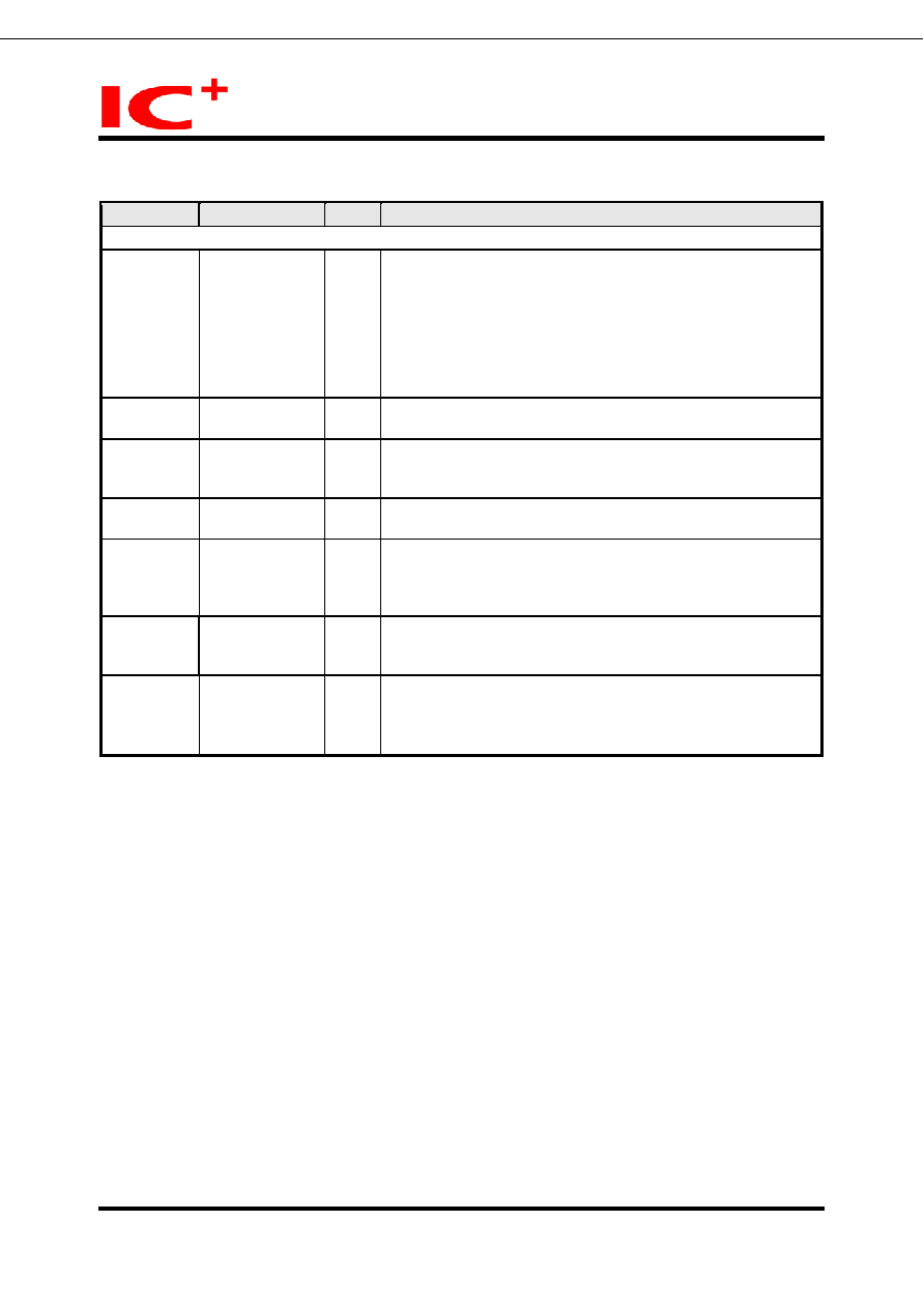
Pin description (continued)
Pin no.
Label
Type
Description
Miscellaneous
33
X1
I
Reference Clock.
25 MHz crystal reference or oscillator input.
Connects to crystal to provide the 25MHz crystal input. If a
25MHz oscillator is used, connect X1 to the oscillator’s output.
The input voltage of this pin should not exceed 1.8V. A voltage
divider formed by 2 resistors is recommended if the output
voltage of oscillator is over 1.8V. Please refer to the Crystal
Specifications in detail.
34
X2
O
Reference Clock.
25 MHz crystal reference.
35
RESET#
I
Hardware reset
Active low.
IP1001 enters reset state when this pin is pulled low.
37
NC_TEST
IPL
It is used for scan test only. It should be left open for normal
operation.
10
CLK_OUT
O
125M clock output
It is used by external MAC device. This signal is always active
after reset.
25
CAP
Capacitor pin
It should be connected to GND through an external 10uF
capacitor. It is used to stabilize the internal analog power.
17
R_SET
I
Band gap Reference
Add an external 6.19k
Ω±1% resistor between this pin and
GND. IP1001 utilizes this resistor to set the current source.


Html Pages

1 2 3 4 5 6 7 8 9 10 11 12 13 14 15 16 17 18 19 20 21 22 23 24 25 26 27 28 29 30 31 32 33 34 35 36 37 38 39 40 41 42 43 44 45 46 47 48


데이터시트 다운로드

Go To PDF Page


링크 URL


ALLDATASHEET 가 귀하에 도움이 되셨나요?  [ DONATE ] 

Alldatasheet는?   |   광고문의   |   운영자에게 연락하기   |   개인정보취급방침   |   링크 투 데이터시트    |   링크교환   |   제조사별 검색
All Rights Reserved©Alldatasheet.com


Mirror Sites
English : Alldatasheet.com  |   English : Alldatasheet.net  |   Chinese : Alldatasheetcn.com  |   German : Alldatasheetde.com  |   Japanese : Alldatasheet.jp
Russian : Alldatasheetru.com  |   Korean : Alldatasheet.co.kr  |   Spanish : Alldatasheet.es  |   French : Alldatasheet.fr  |   Italian : Alldatasheetit.com
Portuguese : Alldatasheetpt.com  |   Polish : Alldatasheet.pl  |   Vietnamese : Alldatasheet.vn
Indian : Alldatasheet.in  |   Mexican : Alldatasheet.com.mx  |   British : Alldatasheet.co.uk  |   New Zealand : Alldatasheet.co.nz
Family Site : ic2ic.com  |   icmetro.com