|
전자부품 데이터시트 검색엔진 |
|
|
전자부품 데이터시트 검색엔진 |
|
INLC10AQ-R4.5 데이터시트(PDF) 24 Page - inova Semiconductors |
|
|
|||||||||||||||||||||||||||||
INLC10AQ-R4.5 데이터시트(HTML) 24 Page - inova Semiconductors |
|
|
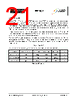
24 / 35 page  Datasheet DS_INLC10AQ Revision 1.0_B Inova Semiconductors Confidential Page 24 of 35 4.2.4 Power Save Mode When all LED channels are set to an intensity of 0, the device enters a power save mode for the current sources driving the LEDs. I.e. the digLED_Set_RGB command must be issued with an RGB value of 0x000000 to enter the power save mode. Recovering from this mode does not require any particular measures. I.e. the host just needs to issue a digLED_Set_RGB command with the data field different from 0x000000 and the current sources are restarted again. There is a delay of approx. 1μs before the restart of the green PWM channel (no phase shift applies to the green channel). This is due to an internal ramp-up required by the analog circuitry. The same procedure is applied after device power-up or a hardware reset, as the initial RGB value is 0x000000. I.e. the LEDs are all turned off after power-up or a hardware reset. 4.3 Blue and Green Brightness Control Scaler In operation, the color brightness of each LED is controlled via an 8-bit RGB parameter. This provides a color space of 3 x 8 bit = 24 bit. The 8-bit RGB value is scaled to the 12-bit PWMmax value. The PWMmax values can be read out with the digLED_Read_Param command. The scaling equations of the green and blue channel are given in Table 22. Color Scaling Blue PWM = (PWMmax x RGB + 128) >> 8 Green PWM = (PWMmax x RGB + 128) >> 8 Table 22 – Scaling of blue and green LED channel |
|
링크 URL |
| ALLDATASHEET 가 귀하에 도움이 되셨나요? [ DONATE ] |
Alldatasheet는? | 광고문의 | 운영자에게 연락하기 | 개인정보취급방침 | 링크 투 데이터시트 | 링크교환 | 제조사별 검색 All Rights Reserved©Alldatasheet.com |
| Russian : Alldatasheetru.com | Korean : Alldatasheet.co.kr | Spanish : Alldatasheet.es | French : Alldatasheet.fr | Italian : Alldatasheetit.com Portuguese : Alldatasheetpt.com | Polish : Alldatasheet.pl | Vietnamese : Alldatasheet.vn Indian : Alldatasheet.in | Mexican : Alldatasheet.com.mx | British : Alldatasheet.co.uk | New Zealand : Alldatasheet.co.nz |
|
Family Site : ic2ic.com |
icmetro.com |
 Korean ▼
 English
 Chinese
 German
 Japanese
 Russian
 Korean
 Spanish
 French
 Italian
 Portuguese
 Polish
 Vietnamese
 Indian
 Mexican
 British
 New Zealand