|
전자부품 데이터시트 검색엔진 |
|
|
전자부품 데이터시트 검색엔진 |
|
KW2D-R100Q4E. 데이터시트(PDF) 13 Page - IDEC Corporation |
|
|
|||||||||||||||||||||||||||||
KW2D-R100Q4E. 데이터시트(HTML) 13 Page - IDEC Corporation |
|
|
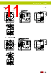
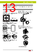
13 / 16 page  KW2D Series ø22 Smart RFID Reader 13 Installation and Wiring Precautions Installation Space Metal around the front unit will affect the reading distance of RFID tags. If the front unit is surrounded with metal, separate the metal from the front unit by 20mm or more. Metal Metal X: 20mm or more (42mm or more from the center) X X X X X X When Multiple Tags Are in the Reading Area The wrong tag may be detected. Keep tags that should not be read 150mm or more from the area around the front unit. Other tag Tag to be read 150mm or more Removing the Back Unit 1) To remove the back unit from the front unit, press the lock lever (①) while turning it to the left. ① ② Lock lever 2) To attach the back unit, align the TOP marks on the front unit and the back unit, and then insert the back unit into the front unit. Turn the lock lever to the right to lock it. • Be sure to turn off the power before starting installation, removal, wiring, maintenance, and inspection work. Failure to turn power off may cause electrical shocks or fire hazard. Panel Mounting Method Insert the front unit into the mounting hole from the front side of the panel, and install the locking ring from the back side of the panel. Locking ring recommended tightening torque: 2.0N·m Locking ring Panel TOP mark Gasket Attaching the Front Cover 1) Attach hook section B (long) of the front cover to the front unit. 2) Push hook section A (short) onto the front unit. 3) The cover (without holder) and cover (with holder) are installed in the same way. Hook section B Hook section A (short) Hook section A (short) Hook section B (long) The front cover can be attached with a pitch of 90°. Precautions for Use Safety Precautions |
|
|
링크 URL |
| ALLDATASHEET 가 귀하에 도움이 되셨나요? [ DONATE ] |
Alldatasheet는? | 광고문의 | 운영자에게 연락하기 | 개인정보취급방침 | 링크 투 데이터시트 | 링크교환 | 제조사별 검색 All Rights Reserved©Alldatasheet.com |
| Russian : Alldatasheetru.com | Korean : Alldatasheet.co.kr | Spanish : Alldatasheet.es | French : Alldatasheet.fr | Italian : Alldatasheetit.com Portuguese : Alldatasheetpt.com | Polish : Alldatasheet.pl | Vietnamese : Alldatasheet.vn Indian : Alldatasheet.in | Mexican : Alldatasheet.com.mx | British : Alldatasheet.co.uk | New Zealand : Alldatasheet.co.nz |
|
Family Site : ic2ic.com |
icmetro.com |
 Korean ▼
 English
 Chinese
 German
 Japanese
 Russian
 Korean
 Spanish
 French
 Italian
 Portuguese
 Polish
 Vietnamese
 Indian
 Mexican
 British
 New Zealand