|
전자부품 데이터시트 검색엔진 |
|
|
전자부품 데이터시트 검색엔진 |
|
MLX90609EEA-R2 데이터시트(PDF) 15 Page - Melexis Microelectronic Systems |
|
|
|||||||||||||||||||||||||||||
MLX90609EEA-R2 데이터시트(HTML) 15 Page - Melexis Microelectronic Systems |
|
|
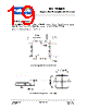
15 / 22 page  MLX90609 Angular Rate Sensor (Standard version) 390109060901 Page 15 of 22 Data Sheet Rev 008 February/08 6. Applications Examples Figure 6-1. MLX90609 with simultaneous analog and digital output The MLX90609 can simultaneously output analog and digital signals. The analog output signal can be fed to a microcontroller (µC) that contains an analog-to-digital converter. A multiplexer can be used to select between the temperature and the angular rate signals. The MLX90609 generates an internal reference voltage used for supplying the ADC, thereby maintaining accuracy regardless of the supply voltage of the µC. Whilst supplying the analog output signal, the MLX90609 can simultaneously send a digital output signal to the µC through the SPI. Notes: 1. The bandwidth of the MLX90609 can be selected by connecting an appropriate capacitor in the FLT pin. CFLT implements a first order low pass filter cascaded with an internal 4-th order SC filter. The –3dB bandwidth set by CFLT is: fOUT =0.16 / (ROUT*CFLT), with ROUT = 200k (typ). It is recommended to use CFLT even if the cut-off frequency is not specified to reduce switching spikes at the output. 2. It is recommended to use X5R or X7R type capacitors. Min. voltage for C3 should be 25V or more, and 10V or more for the other capacitors. Recommended values of decoupling capacitors C1 and C2 are 1.0µF and 0.1µF for C3. These capacitors should be placed as close as possible to their respective pins. 3. HVIN is a high impedance node. Be sure that an equivalent leakage resistance at this node isn’t less then 2M |
|
|
링크 URL |
| ALLDATASHEET 가 귀하에 도움이 되셨나요? [ DONATE ] |
Alldatasheet는? | 광고문의 | 운영자에게 연락하기 | 개인정보취급방침 | 링크 투 데이터시트 | 링크교환 | 제조사별 검색 All Rights Reserved©Alldatasheet.com |
| Russian : Alldatasheetru.com | Korean : Alldatasheet.co.kr | Spanish : Alldatasheet.es | French : Alldatasheet.fr | Italian : Alldatasheetit.com Portuguese : Alldatasheetpt.com | Polish : Alldatasheet.pl | Vietnamese : Alldatasheet.vn Indian : Alldatasheet.in | Mexican : Alldatasheet.com.mx | British : Alldatasheet.co.uk | New Zealand : Alldatasheet.co.nz |
|
Family Site : ic2ic.com |
icmetro.com |
 Korean ▼
 English
 Chinese
 German
 Japanese
 Russian
 Korean
 Spanish
 French
 Italian
 Portuguese
 Polish
 Vietnamese
 Indian
 Mexican
 British
 New Zealand