|
전자부품 데이터시트 검색엔진 |
|
|
전자부품 데이터시트 검색엔진 |
|
ADL5571ACPZ-R7 데이터시트(PDF) 14 Page - Analog Devices |
|
|
|||||||||||||||||||||||||||||
ADL5571ACPZ-R7 데이터시트(HTML) 14 Page - Analog Devices |
|
|
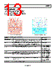
14 / 16 page  ADL5571 Rev. 0 | Page 14 of 16 MEASUREMENT SETUP When using the ADL5571 evaluation board, the following set up must be used: 1. Connect the output of the WiMAX signal generator to the RF input through a cable. 2. Connect the RF output SMA of the ADL5571 to the Spectrum Analyzer (preferably through an attenuator). 3. Ensure that Jumper W1 is in place. Alternatively, use a jumper cable to connect VPOS to VPOS1. 4. Connect power supply to VPOS. Set voltage to the desired supply level (3.3 V, 5 V). Set the current limit on this source to 1 A. 5. Connect another power supply to VREG. Set voltage to 2.85 V. Set the current limit on this source to 100 mA. 6. Turn all voltage supplies on. 7. Turn RF source on. Table 7. Operating Modes: Power Supply1 Nomenclature High Low VREG 2.85 V 0 V STBY 2.5 V 0 V 1 Note that device is not sequence dependent. |
|
|
링크 URL |
| ALLDATASHEET 가 귀하에 도움이 되셨나요? [ DONATE ] |
Alldatasheet는? | 광고문의 | 운영자에게 연락하기 | 개인정보취급방침 | 링크 투 데이터시트 | 링크교환 | 제조사별 검색 All Rights Reserved©Alldatasheet.com |
| Russian : Alldatasheetru.com | Korean : Alldatasheet.co.kr | Spanish : Alldatasheet.es | French : Alldatasheet.fr | Italian : Alldatasheetit.com Portuguese : Alldatasheetpt.com | Polish : Alldatasheet.pl | Vietnamese : Alldatasheet.vn Indian : Alldatasheet.in | Mexican : Alldatasheet.com.mx | British : Alldatasheet.co.uk | New Zealand : Alldatasheet.co.nz |
|
Family Site : ic2ic.com |
icmetro.com |
 Korean ▼
 English
 Chinese
 German
 Japanese
 Russian
 Korean
 Spanish
 French
 Italian
 Portuguese
 Polish
 Vietnamese
 Indian
 Mexican
 British
 New Zealand