|
전자부품 데이터시트 검색엔진 |
|
|
전자부품 데이터시트 검색엔진 |
|
H8SX/1663 데이터시트(PDF) 929 Page - Renesas Technology Corp |
|
|
|||||||||||||||||||||||||||||
H8SX/1663 데이터시트(HTML) 929 Page - Renesas Technology Corp |
|
|
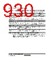
929 / 1158 page  Section 21 Flash Memory (0.18- µm F-ZTAT Version) Rev.1.00 Jun. 07, 2006 Page 877 of 1102 REJ09B0294-0100 21.2 Mode Transition Diagram When the mode pins are set in the reset state and reset start is performed, this LSI enters each operating mode as shown in figure 21.2. Although the flash memory can be read in user mode, it cannot be programmed or erased. The flash memory can be programmed or erased in boot mode, user program mode, and programmer mode. The differences between boot mode, user program mode, and programmer mode are shown in table 21.1. Reset state Programmer mode User mode User program mode USB boot mode On-board programming mode RES = 0 User mode sett ing USB boot m od e sett ing RES = 0 RES = 0 Programmer mode setting SCI boot mode *1 RAM emulation can be available ROM disabled mode RES = 0 ROM disabled mode setting *2 Notes: * In this LSI, the user program mode is defined as the period from the timing when a program concerning programming and erasure is started in user mode to the timing when the program is completed. 1. Programming and erasure is started. 2. Programming and erasure is completed. Figure 21.2 Mode Transition of Flash Memory |
|
링크 URL |
| ALLDATASHEET 가 귀하에 도움이 되셨나요? [ DONATE ] |
Alldatasheet는? | 광고문의 | 운영자에게 연락하기 | 개인정보취급방침 | 링크 투 데이터시트 | 링크교환 | 제조사별 검색 All Rights Reserved©Alldatasheet.com |
| Russian : Alldatasheetru.com | Korean : Alldatasheet.co.kr | Spanish : Alldatasheet.es | French : Alldatasheet.fr | Italian : Alldatasheetit.com Portuguese : Alldatasheetpt.com | Polish : Alldatasheet.pl | Vietnamese : Alldatasheet.vn Indian : Alldatasheet.in | Mexican : Alldatasheet.com.mx | British : Alldatasheet.co.uk | New Zealand : Alldatasheet.co.nz |
|
Family Site : ic2ic.com |
icmetro.com |
 Korean ▼
 English
 Chinese
 German
 Japanese
 Russian
 Korean
 Spanish
 French
 Italian
 Portuguese
 Polish
 Vietnamese
 Indian
 Mexican
 British
 New Zealand