|
전자부품 데이터시트 검색엔진 |
|
|
전자부품 데이터시트 검색엔진 |
|
H8SX/1663 데이터시트(PDF) 1026 Page - Renesas Technology Corp |
|
|
|||||||||||||||||||||||||||||
H8SX/1663 데이터시트(HTML) 1026 Page - Renesas Technology Corp |
|
|
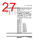
1026 / 1158 page  Section 23 Power-Down Modes Rev.1.00 Jun. 07, 2006 Page 974 of 1102 REJ09B0294-0100 23.2.1 Standby Control Register (SBYCR) SBYCR controls software standby mode. Bit Bit Name Initial Value R/W 15 SSBY 0 R/W 14 OPE 1 R/W 13 0 R/W 12 STS4 0 R/W 11 STS3 1 R/W 10 STS2 1 R/W 9 STS1 1 R/W 8 STS0 1 R/W Bit Bit Name Initial Value R/W 7 SLPIE 0 R/W 6 0 R/W 5 0 R/W 4 0 R/W 3 0 R/W 2 0 R/W 1 0 R/W 0 0 R/W Bit Bit Name Initial Value R/W Description 15 SSBY 0 R/W Software Standby Specifies the transition mode after executing the SLEEP instruction 0: Shifts to sleep mode after the SLEEP instruction is executed 1: Shifts to software standby mode after the SLEEP instruction is executed This bit does not change when clearing the software standby mode by using external interrupts and shifting to normal operation. For clearing, write 0 to this bit. When the WDT is used as the watchdog timer, the setting of this bit is disabled. In this case, a transition is always made to sleep mode or all-module-clock-stop mode after the SLEEP instruction is executed. When the SLPIE bit is set to 1, this bit should be cleared to 0. 14 OPE 1 R/W Output Port Enable Specifies whether the output of the address bus and bus control signals ( CS0 to CS7, AS, RD, HWR, and LWR) is retained or set to the high-impedance state in software standby mode. 0: In software standby mode, address bus and bus control signals are high-impedance 1: In software standby mode, address bus and bus control signals retain output state |
|
링크 URL |
| ALLDATASHEET 가 귀하에 도움이 되셨나요? [ DONATE ] |
Alldatasheet는? | 광고문의 | 운영자에게 연락하기 | 개인정보취급방침 | 링크 투 데이터시트 | 링크교환 | 제조사별 검색 All Rights Reserved©Alldatasheet.com |
| Russian : Alldatasheetru.com | Korean : Alldatasheet.co.kr | Spanish : Alldatasheet.es | French : Alldatasheet.fr | Italian : Alldatasheetit.com Portuguese : Alldatasheetpt.com | Polish : Alldatasheet.pl | Vietnamese : Alldatasheet.vn Indian : Alldatasheet.in | Mexican : Alldatasheet.com.mx | British : Alldatasheet.co.uk | New Zealand : Alldatasheet.co.nz |
|
Family Site : ic2ic.com |
icmetro.com |
 Korean ▼
 English
 Chinese
 German
 Japanese
 Russian
 Korean
 Spanish
 French
 Italian
 Portuguese
 Polish
 Vietnamese
 Indian
 Mexican
 British
 New Zealand