|
전자부품 데이터시트 검색엔진 |
|
|
전자부품 데이터시트 검색엔진 |
|
TDA7407 데이터시트(PDF) 17 Page - STMicroelectronics |
|
|
|||||||||||||||||||||||||||||
TDA7407 데이터시트(HTML) 17 Page - STMicroelectronics |
|
|
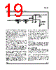
17 / 30 page  LEVEL Input and Gain To suppress undesired high frequency modula- tion on the highcut and stereoblend function the LEVEL signal is lowpass filtered firstly. The filter is a combination of a 1st order RC low- pass at 53kHz (working as anti-aliasing filter) and a 1st-order switched capacitor lowpass at 2.2kHz. The second stage is a programmable gain stage to adapt the LEVEL signal internally to different IF device (see Testmode section 5 LEVELINTERN). The gain is widely programmable in 16 steps from 0dB to 10dB (step = 0.67dB). These 4 bits are located together with the Roll-Off bits in the "Stereodecoder Adjustment" byte to simplify a possible adaptation during the production of the carradio. Stereoblend Control The stereoblend control block converts the inter- nal LEVEL voltage (LEVEL INTERN) into an de- modulator compatible analog signal which is used to control the channel separation between 0dB and the maximum separation. Internally this con- trol range has a fixed upper limit which is the in- ternal reference voltage REF5V. The lower limit can be programmed between 29.2% and 58%, of REF5V in 4.167% steps (see figs. 14, 15). To adjust the external LEVEL voltage to the inter- nal range two values must be defined: the LEVEL gain LG and VSBL (see fig. 15). To adjust the voltage where the full channel separation is reached (VST) the LEVEL gain LG has to be de- fined. The following equation can be used to esti- mate the gain: LG = REF5V Fieldstrengthvoltage[STEREO] The gain can be programmed through 4 bits in the "Stereodecoder-Adjustment" byte. The MONO voltage VMO (0dB channel separa- tion) can be choosen selecting VSBL All necessary internal reference voltages like REF5V are derived from a bandgap circuit. Therefore they have a temperature coefficient near zero. This is useful if the fieldstrength signal is also temperature compensated. But most IF devices apply a LEVEL voltage with a TC of 3300ppm. The TDA7407 offers this TC for the reference voltages, too. The TC is selectable with bit D7 of the "stereodecoder adjustment" byte. Highcut Control The highcut control setup is similar to the stereoblend control setup : the starting point VHCH can be set with 2 bits to be 42, 50, 58 or 66% of REF5V whereas the range can be set to be 17, 22, 28 or 33% of VHCH (see fig. 19). INTERNAL VOLTAGES t D97AU639 VSBL REF 5V SETUP OF VST INTERNAL VOLTAGES t 33% REF 5V SETUP OF VMO LEVEL LEVEL INTERN FIELDSTRENGHT VOLTAGE VST VMO LEVEL INTERN 42% 50% 58% VSBL VST VMO FIELDSTRENGHT VOLTAGE Figure 18. Relation Between Internal and External LEVEL Voltage and Setup of Stereoblend LOWPASS TIME CONSTANT D97AU640 τDeemp FIELDSTRENGHT VHCH VHCL 3 • τDeemp Figure 19. Highcut Characteristics TDA7407 17/30 |
|
링크 URL |
| ALLDATASHEET 가 귀하에 도움이 되셨나요? [ DONATE ] |
Alldatasheet는? | 광고문의 | 운영자에게 연락하기 | 개인정보취급방침 | 링크 투 데이터시트 | 링크교환 | 제조사별 검색 All Rights Reserved©Alldatasheet.com |
| Russian : Alldatasheetru.com | Korean : Alldatasheet.co.kr | Spanish : Alldatasheet.es | French : Alldatasheet.fr | Italian : Alldatasheetit.com Portuguese : Alldatasheetpt.com | Polish : Alldatasheet.pl | Vietnamese : Alldatasheet.vn Indian : Alldatasheet.in | Mexican : Alldatasheet.com.mx | British : Alldatasheet.co.uk | New Zealand : Alldatasheet.co.nz |
|
Family Site : ic2ic.com |
icmetro.com |
 Korean ▼
 English
 Chinese
 German
 Japanese
 Russian
 Korean
 Spanish
 French
 Italian
 Portuguese
 Polish
 Vietnamese
 Indian
 Mexican
 British
 New Zealand