|
전자부품 데이터시트 검색엔진 |
|
|
전자부품 데이터시트 검색엔진 |
|
ATtiny13A-SSH 데이터시트(PDF) 86 Page - ATMEL Corporation |
|
|
|||||||||||||||||||||||||||||
ATtiny13A-SSH 데이터시트(HTML) 86 Page - ATMEL Corporation |
|
|
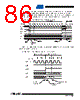
86 / 174 page  86 8126D–AVR–11/09 ATtiny13A When Auto Triggering is used, the prescaler is reset when the trigger event occurs, as shown in Figure 14-6 below. This assures a fixed delay from the trigger event to the start of conversion. In this mode, the sample-and-hold takes place two ADC clock cycles after the rising edge on the trigger source signal. Three additional CPU clock cycles are used for synchronization logic. Figure 14-6. ADC Timing Diagram, Auto Triggered Conversion In Free Running mode, a new conversion will be started immediately after the conversion com- pletes, while ADSC remains high. Figure 14-7. ADC Timing Diagram, Free Running Conversion 1 2 3 4 5 6 7 8 9 10 11 12 13 Sign and MSB of Result LSB of Result ADC Clock Trigger Source ADIF ADCH ADCL Cycle Number 12 One Conversion Next Conversion Conversion Complete Prescaler Reset ADATE Prescaler Reset Sample & Hold MUX and REFS Update 11 12 13 Sign and MSB of Result LSB of Result ADC Clock ADSC ADIF ADCH ADCL Cycle Number 12 One Conversion Next Conversion 34 Conversion Complete Sample & Hold MUX and REFS Update |
|
링크 URL |
| ALLDATASHEET 가 귀하에 도움이 되셨나요? [ DONATE ] |
Alldatasheet는? | 광고문의 | 운영자에게 연락하기 | 개인정보취급방침 | 링크 투 데이터시트 | 링크교환 | 제조사별 검색 All Rights Reserved©Alldatasheet.com |
| Russian : Alldatasheetru.com | Korean : Alldatasheet.co.kr | Spanish : Alldatasheet.es | French : Alldatasheet.fr | Italian : Alldatasheetit.com Portuguese : Alldatasheetpt.com | Polish : Alldatasheet.pl | Vietnamese : Alldatasheet.vn Indian : Alldatasheet.in | Mexican : Alldatasheet.com.mx | British : Alldatasheet.co.uk | New Zealand : Alldatasheet.co.nz |
|
Family Site : ic2ic.com |
icmetro.com |
 Korean ▼
 English
 Chinese
 German
 Japanese
 Russian
 Korean
 Spanish
 French
 Italian
 Portuguese
 Polish
 Vietnamese
 Indian
 Mexican
 British
 New Zealand