|
전자부품 데이터시트 검색엔진 |
|
|
전자부품 데이터시트 검색엔진 |
|
PDSP1601 데이터시트(PDF) 6 Page - Mitel Networks Corporation |
|
|
|||||||||||||||||||||||||||||
PDSP1601 데이터시트(HTML) 6 Page - Mitel Networks Corporation |
|
|
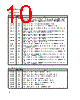
6 / 17 page  PDSP1601/PDSP1601A 6 Divide by Two The ALU has four (A2SGN, A2RAL, A2RAR, A2RSX) instructions used for right shifting (dividing by two) extended precision words. These words, (up to 64 bits) may be stored in the two on-chip register files. When the least significant 16 bit word is shifted, the vacant MSB must be filled with the LSB from the next most significant 16 bit byte. This is achieved via the A2RAL, A2RAR or A2RSX instructions which indicate the source of the new MSB (see ALU INSTRUCTION SET). When the most significant 16 bit byte is right shifted, the MSB must be filled with a duplicate of the original MSB so as to maintain the correct sign (Sign Extension). This operation is achieved via the A2SGN instruction (see Table 1). Constants The ALU has four instructions (OPONE, OPBYT, OPNIB, OPALT) that force a constant value onto the ALU output. These values are primarily intended to be used as masks, or the seeds for mask generation, for example, the OPONE instruction will set a single bit in the least significant position. This bit may be rotated any where in the 16 bit field by the Barrel Shifter, allowing the AND function of the ALU to perform bit-pick operations on input data. CLR The ALU instruction CLRXX is used as a Master Reset for the entire device. This instruction has the effect of: 1. Clearing ALU and Barrel Shifter register files to zero. 2. Clearing A and B port input registers to zero. 3. Clearing the R1 and R2 shift control registers to zero. 4. Clearing the internally registered CO bit to zero. 5. Programming the BFP flag to detect overflow conditions. The Barrel Shifter The Barrel Shifter supports 16 instructions as detailed in Table 2. The input to the Barrel Shifter is selected by the S MUX. Data will fall through from the selected register, through the S MUX and the Barrel Shifter to the shifter output register file in 50ns for the PDSP1601A (100ns for the PDSP1601). The Barrel Shifter instructions are latched, such that the instructions will not start executing until the rising edge of CLK latches the instruction into the device. The Barrel Shifter is capable of Logical Arithmetic or Barrel Shifts in either direction. A. Logical shifts discard bits that exit the 16 bit field and fill spaces with zeros. B. Arithmetic shifts discard bits that exit the 16 bit field and fill spaces with duplicates of the original MSB. C. Barrel Shifts rotate the 16 bit fields such that bits tha exit the 16 bit field to the left or right reappear in the vacant spaces on the right or left. The amount of shift applied is encoded onto the 4 bit Barrel Shifter input as illustrated in Table 3. The type of shift and the amount are determined by the shift control block. The shift control block (see Fig.3) accepts and decodes the four bit ISO- 3 instruction. The shift control block contains a priority encoder and two user programmable 4 bit registers R1 and R2. There are four possible sources of shift value that can be passed onto the Barrel Shifter, there are: 1. The Priority Encoder 2. The SV input 3. The R1 register 4. The R2 register Mnemonic LSRSV LSLSV BSRSV BSLSV LSRR1 LSLR1 LSRR2 LSLR2 LR1SV LR2SV ASRSV ASRR1 ASRR2 NRMXX NRMR1 NRMR2 IS3-IS0 0000 0001 0010 0011 0100 0101 0110 0111 1000 1001 1010 1011 1100 1101 1110 1111 Operation Logical Shift Right by SV Logical Shift Left by SV Barrel Shift Right by SV Barrel Shift Left by SV Logical Shift Right by R1 Logical Shift Left by R1 Logical Shift Right by R2 Logical Shift Left by R2 Load Register 1 From SV Load Register 2 From SV Arithmetic Shift Right by SV Arithmetic Shift Right by R1 Arithmetic Shift Right by R2 Normalise Output PE Normalise Output PE, Load R1 Normalise Output PE, Load R2 Inst 0 1 2 3 4 5 6 7 8 9 A B C D E F I/O I I I I X X X X I I I X X O O O Table 2 Barrel shifter instructions KEY SV = Shift Value R1 = Register 1 R2 = Register 2 PE = Priority Encoder Output I => SV Port operates as an Input O => SV Port operates as an Output X => SV Port in a High Impedance State MNEMONICS LSXYY Logical Shift, X = Direction YY = Source of Shift Value BSXYY Barrel Shift, X = Direction YY = Source of Shift Value ASXYY Arithmetic Shift, X = Direction YY = Source of Shift Value LXXYY Load XX = Target YY = Source NRMYY Normalise by PE, Output PE value on SV Port, Load YY Reg |
|
|
링크 URL |
| ALLDATASHEET 가 귀하에 도움이 되셨나요? [ DONATE ] |
Alldatasheet는? | 광고문의 | 운영자에게 연락하기 | 개인정보취급방침 | 링크 투 데이터시트 | 링크교환 | 제조사별 검색 All Rights Reserved©Alldatasheet.com |
| Russian : Alldatasheetru.com | Korean : Alldatasheet.co.kr | Spanish : Alldatasheet.es | French : Alldatasheet.fr | Italian : Alldatasheetit.com Portuguese : Alldatasheetpt.com | Polish : Alldatasheet.pl | Vietnamese : Alldatasheet.vn Indian : Alldatasheet.in | Mexican : Alldatasheet.com.mx | British : Alldatasheet.co.uk | New Zealand : Alldatasheet.co.nz |
|
Family Site : ic2ic.com |
icmetro.com |
 Korean ▼
 English
 Chinese
 German
 Japanese
 Russian
 Korean
 Spanish
 French
 Italian
 Portuguese
 Polish
 Vietnamese
 Indian
 Mexican
 British
 New Zealand