|
전자부품 데이터시트 검색엔진 |
|
|
전자부품 데이터시트 검색엔진 |
|
CC1150-RTY1 데이터시트(PDF) 56 Page - Texas Instruments |
|
|
|||||||||||||||||||||||||||||
CC1150-RTY1 데이터시트(HTML) 56 Page - Texas Instruments |
|
|
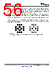
56 / 67 page  CC1150 SWRS037B – JANUARY 2006 – REVISED MARCH 2015 www.ti.com Each decoupling capacitor ground pad should be connected to the ground plane by separate vias. Direct connections between neighboring power pins will increase noise coupling and should be avoided unless absolutely necessary. Routing in the ground plane underneath and between the chip, the balun/RF matching circuit and the decoupling capacitor’s ground vias should also be avoided. This improves the grounding and ensures the shortest possible return path for stray currents. The external components should ideally be as small as possible (0402 is recommended) and surface mount devices are highly recommended. Please note that components smaller than those specified may have differing characteristics. Precaution should be used when placing the microcontroller in order to avoid noise interfering with the RF circuitry. It is strongly advised that the CC1150EM reference design (see [1] and [2]) layout is followed very closely in order to get the best performance. Gerber files and schematics for the reference designs are available for download from the TI website. Circles are Vias Figure 6-4. Left: Top Solder Resist Mask (Negative) and Right: Top Paste Mask 56 Applications, Implementation, and Layout Copyright © 2006–2015, Texas Instruments Incorporated Submit Documentation Feedback Product Folder Links: CC1150 |
|
링크 URL |
| ALLDATASHEET 가 귀하에 도움이 되셨나요? [ DONATE ] |
Alldatasheet는? | 광고문의 | 운영자에게 연락하기 | 개인정보취급방침 | 링크 투 데이터시트 | 링크교환 | 제조사별 검색 All Rights Reserved©Alldatasheet.com |
| Russian : Alldatasheetru.com | Korean : Alldatasheet.co.kr | Spanish : Alldatasheet.es | French : Alldatasheet.fr | Italian : Alldatasheetit.com Portuguese : Alldatasheetpt.com | Polish : Alldatasheet.pl | Vietnamese : Alldatasheet.vn Indian : Alldatasheet.in | Mexican : Alldatasheet.com.mx | British : Alldatasheet.co.uk | New Zealand : Alldatasheet.co.nz |
|
Family Site : ic2ic.com |
icmetro.com |
 Korean ▼
 English
 Chinese
 German
 Japanese
 Russian
 Korean
 Spanish
 French
 Italian
 Portuguese
 Polish
 Vietnamese
 Indian
 Mexican
 British
 New Zealand