|
전자부품 데이터시트 검색엔진 |
|
|
전자부품 데이터시트 검색엔진 |
|
DS481N 데이터시트(PDF) 6 Page - National Semiconductor (TI) |
|
|
|
|||||||||||||||||||||||||||||
DS481N 데이터시트(HTML) 6 Page - National Semiconductor (TI) |
|
|
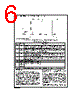
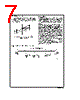
6 / 10 page  Parameter Measurement Information (Continued) TABLE 1. Device Pin Descriptions Pin No. Name Description 1 RO Receiver Output: When RE (Receiver Enable) is LOW, the receiver is enabled (ON), if DO/RI ≥ DO (Note 1)/RI (Note 1) by 200 mV, RO will be HIGH. If DO/RI ≤ DO (Note 1)/RI (Note 1) by 200 mV, RO will be LOW. Additionally RO will be HIGH for OPEN (Non-terminated) Inputs. 2RE (Note 1) Receiver Output Enable: When RE (Note 1) is LOW the receiver output is enabled. When RE (Note 1) is HIGH, the receiver output is in TRI-STATE (OFF). When RE (Note 1) is HIGH and DE is LOW, the device will enter a low-current sleep mode after 600 ns. 3 DE Driver Output Enable: When DE is HIGH, the driver outputs are enabled. When DE is LOW, the driver outputs are in TRI-STATE (OFF). When RE (Note 1) is HIGH and DE is LOW, the device will enter a low-current sleep mode after 600 ns. 4 DI Driver Input: When DE (Driver Enable) is HIGH, the driver is enabled, if DI is LOW, then DO/RI will be LOW and DO (Note 1)/RI (Note 1) will be HIGH. If DI is HIGH, then DO/RI is HIGH and DO (Note 1)/RI (Note 1) is LOW. 5 GND Ground Connection. 6 DO/RI Driver Output/Receiver Input, 485 Bus Pin. 7DO (Note 1) /RI (Note 1) Driver Output/Receiver Input, 485 Bus Pin. 8V CC Positive Power Supply Connection: Recommended operating range for V CC is +4.75V to +5.25V. Unit Load A unit load for an RS-485 receiver is defined by the input cur- rent versus the input voltage curve. The gray shaded region is the defined operating range from −7V to +12V. The top border extending from −3V at 0 mA to +12V at +1 mA is de- fined as one unit load. Likewise, the bottom border extending from +5V at 0 mA to −7V at −0.8 mA is also defined as one unit load (see Figure 15 ). An RS-485 driver is capable of driving up to 32 unit loads. This allows up to 32 nodes on a single bus. Although sufficient for many applications, it is sometimes desirable to have even more nodes. The DS481 has 1⁄2 unit load and 1⁄4 unit load (UL) options available. These devices will allow up to 64 nodes or 128 nodes guaranteed over temperature depending upon which option is selected. The 1⁄2 UL option is available in industrial temperature and the 1⁄4 UL is available in commercial tem- perature. First, for a 1⁄2 UL device the top and bottom borders shown in Figure 15 are scaled. Both 0 mA reference points at +5V and −3V stay the same. The other reference points are +12V at +0.5 mA for the top border and −7V at −0.4 mA for the bot- tom border (see Figure 15 ). Second, for a 1⁄4 UL device the top and bottom borders shown in Figure 15 are scaled also. Again, both 0 mA reference points at +5V and −3V stay the same. The other reference points are +12V at +0.25 mA for the top border and −7V at −0.2 mA for the bottom border (see Figure 15 ). The advantage of the 1⁄2 UL and 1⁄4 UL devices is the in- creased number of nodes on one bus. In a single master DS012919-15 *Note: Non Terminated, Open Input only FIGURE 14. Entering Sleep Mode Conditions (modes and exit parameters shown) www.national.com 6 |
|
|
링크 URL |
| ALLDATASHEET 가 귀하에 도움이 되셨나요? [ DONATE ] |
Alldatasheet는? | 광고문의 | 운영자에게 연락하기 | 개인정보취급방침 | 링크 투 데이터시트 | 링크교환 | 제조사별 검색 All Rights Reserved©Alldatasheet.com |
| Russian : Alldatasheetru.com | Korean : Alldatasheet.co.kr | Spanish : Alldatasheet.es | French : Alldatasheet.fr | Italian : Alldatasheetit.com Portuguese : Alldatasheetpt.com | Polish : Alldatasheet.pl | Vietnamese : Alldatasheet.vn Indian : Alldatasheet.in | Mexican : Alldatasheet.com.mx | British : Alldatasheet.co.uk | New Zealand : Alldatasheet.co.nz |
|
Family Site : ic2ic.com |
icmetro.com |
 Korean ▼
 English
 Chinese
 German
 Japanese
 Russian
 Korean
 Spanish
 French
 Italian
 Portuguese
 Polish
 Vietnamese
 Indian
 Mexican
 British
 New Zealand