|
전자부품 데이터시트 검색엔진 |
|
|
전자부품 데이터시트 검색엔진 |
|
MIC2199 데이터시트(PDF) 10 Page - Micrel Semiconductor |
|
|
|||||||||||||||||||||||||||||
MIC2199 데이터시트(HTML) 10 Page - Micrel Semiconductor |
|
|
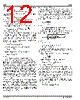
10 / 15 page  MIC2199 Micrel MIC2199 10 November 2004 Applications Information Following applications information includes component se- lection and design guidelines. Inductor Selection Values for inductance, peak, and RMS currents are required to select the output inductor. The input and output voltages and the inductance value determine the peak-to-peak induc- tor ripple current. Generally, higher inductance values are used with higher input voltages. Larger peak-to-peak ripple currents will increase the power dissipation in the inductor and MOSFETs. Larger output ripple currents will also require more output capacitance to smooth out the larger ripple current. Smaller peak-to-peak ripple currents require a larger inductance value and therefore a larger and more expensive inductor. A good compromise between size, loss and cost is to set the inductor ripple current to be equal to 20% of the maximum output current. The inductance value is calculated by the equation below. L V(V V ) V f 0.2 I OUT IN(max) OUT IN(max) S OUT(max) = × − ×× × where: f S = switching frequency 0.2 = ratio of AC ripple current to DC output current V IN(max) = maximum input voltage The peak-to-peak inductor current (AC ripple current) is: I V(V V ) Vf L PP OUT IN(max) OUT IN(max) S = × − ×× The peak inductor current is equal to the average output current plus one half of the peak-to-peak inductor ripple current. I I 0.5 I PK OUT(max) PP =+ × The RMS inductor current is used to calculate the I2×R losses in the inductor. II 1 1 3 I I INDUCTOR(rms) OUT(max) P OUT(max) 2 =× + ⎛ ⎝ ⎜ ⎞ ⎠ ⎟ Maximizing efficiency requires the proper selection of core material and minimizing the winding resistance. The high frequency operation of the MIC2199 requires the use of ferrite materials for all but the most cost sensitive applications. Lower cost iron powder cores may be used but the increase in core loss will reduce the efficiency of the power supply. This is especially noticeable at low output power. The winding resistance decreases efficiency at the higher output current levels. The winding resistance must be minimized although this usually comes at the expense of a larger inductor. The power dissipated in the inductor is equal to the sum of the core and copper losses. At higher output loads, the core losses are usually insignificant and can be ignored. At lower output currents, the core losses can be a significant contribu- tor. Core loss information is usually available from the mag- netics vendor. Copper loss in the inductor is calculated by the equation below: PI R INDUCTORCu INDUCTOR(rms) WINDING 2 =× The resistance of the copper wire, R WINDING, increases with temperature. The value of the winding resistance used should be at the operating temperature. R R 1 0.0042 (T T ) WINDING(hot) WINDING(20 C) HOT 20 C =× + × − () °° where: T HOT = temperature of the wire under operating load T 20°C = ambient temperature R WINDING(20°C) is room temperature winding resistance (usually specified by the manufacturer) Current-Sense Resistor Selection Low inductance power resistors, such as metal film resistors should be used. Most resistor manufacturers make low inductance resistors with low temperature coefficients, de- signed specifically for current-sense applications. Both resis- tance and power dissipation must be calculated before the resistor is selected. The value of R SENSE is chosen based on the maximum output current and the maximum threshold level. The power dissipated is based on the maximum peak output current at the minimum overcurrent threshold limit. R 55mV I SENSE OUT(max) = The maximum overcurrent threshold is: I 95mV R OVERCURRENT(max) CS = The maximum power dissipated in the sense resistor is: PI R D(R ) OVERCURRENT(max) 2 CS SENSE =× MOSFET Selection External N-Channel logic-level power MOSFETs must be used for the high- and low-side switches. The MOSFET gate- to-source drive voltage of the MIC2199 is regulated by an internal 5V V DD regulator. Logic-level MOSFETs, whose operation is specified at V GS = 4.5V must be used. It is important to note the on-resistance of a MOSFET increases with increasing temperature. A 75°C rise in junc- tion temperature will increase the channel resistance of the MOSFET by 50% to 75% of the resistance specified at 25°C. This change in resistance must be accounted for when calculating MOSFET power dissipation. Total gate charge is the charge required to turn the MOSFET on and off under specified operating conditions (V DS and V GS). The gate charge is supplied by the MIC2199 gate drive circuit. At 500kHz switching frequency, the gate charge can be a significant source of power dissipation in the MIC2199. At low output load this power dissipation is noticeable as a |
|
|
링크 URL |
| ALLDATASHEET 가 귀하에 도움이 되셨나요? [ DONATE ] |
Alldatasheet는? | 광고문의 | 운영자에게 연락하기 | 개인정보취급방침 | 링크 투 데이터시트 | 링크교환 | 제조사별 검색 All Rights Reserved©Alldatasheet.com |
| Russian : Alldatasheetru.com | Korean : Alldatasheet.co.kr | Spanish : Alldatasheet.es | French : Alldatasheet.fr | Italian : Alldatasheetit.com Portuguese : Alldatasheetpt.com | Polish : Alldatasheet.pl | Vietnamese : Alldatasheet.vn Indian : Alldatasheet.in | Mexican : Alldatasheet.com.mx | British : Alldatasheet.co.uk | New Zealand : Alldatasheet.co.nz |
|
Family Site : ic2ic.com |
icmetro.com |
 Korean ▼
 English
 Chinese
 German
 Japanese
 Russian
 Korean
 Spanish
 French
 Italian
 Portuguese
 Polish
 Vietnamese
 Indian
 Mexican
 British
 New Zealand