|
전자부품 데이터시트 검색엔진 |
|
|
전자부품 데이터시트 검색엔진 |
|
M95020-R 데이터시트(PDF) 30 Page - STMicroelectronics |
|
|
|||||||||||||||||||||||||||||
M95020-R 데이터시트(HTML) 30 Page - STMicroelectronics |
|
|
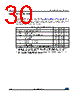
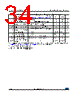
30 / 46 page  Maximum rating M950x0-W M950x0-R M950x0-DF 30/46 DocID6512 Rev 13 8 Maximum rating Stressing the device outside the ratings listed in Table 8: Absolute maximum ratings may cause permanent damage to the device. These are stress ratings only, and operation of the device at these, or any other conditions outside those indicated in the operating sections of this specification, is not implied. Exposure to absolute maximum rating conditions for extended periods may affect device reliability. Table 8. Absolute maximum ratings Symbol Parameter Min. Max. Unit TAMR Ambient operating temperature –40 130 °C TSTG Storage temperature –65 150 °C TLEAD Lead temperature during soldering see note (1) 1. Compliant with JEDEC standard J-STD-020D (for small-body, Sn-Pb or Pb assembly), the ST ECOPACK® 7191395 specification, and the European directive on Restrictions on Hazardous Substances (RoHS directive 2011/65/EU of July 2011). °C VO Output voltage –0.50 VCC+0.6 V VI Input voltage –0.50 VCC+1.0 V IOL DC output current (Q = 0) - 5 mA IIH DC output current (Q = 1) - 5 mA VCC Supply voltage –0.50 6.5 V VESD Electrostatic pulse (Human Body Model) voltage(2) 2. Positive and negative pulses applied on pin pairs, according to the AEC-Q100-002 (compliant with JEDEC Std JESD22-A114, C1=100pF, R1=1500 Ω, R2=500 Ω). -4000 V |
|
링크 URL |
| ALLDATASHEET 가 귀하에 도움이 되셨나요? [ DONATE ] |
Alldatasheet는? | 광고문의 | 운영자에게 연락하기 | 개인정보취급방침 | 링크 투 데이터시트 | 링크교환 | 제조사별 검색 All Rights Reserved©Alldatasheet.com |
| Russian : Alldatasheetru.com | Korean : Alldatasheet.co.kr | Spanish : Alldatasheet.es | French : Alldatasheet.fr | Italian : Alldatasheetit.com Portuguese : Alldatasheetpt.com | Polish : Alldatasheet.pl | Vietnamese : Alldatasheet.vn Indian : Alldatasheet.in | Mexican : Alldatasheet.com.mx | British : Alldatasheet.co.uk | New Zealand : Alldatasheet.co.nz |
|
Family Site : ic2ic.com |
icmetro.com |
 Korean ▼
 English
 Chinese
 German
 Japanese
 Russian
 Korean
 Spanish
 French
 Italian
 Portuguese
 Polish
 Vietnamese
 Indian
 Mexican
 British
 New Zealand