|
전자부품 데이터시트 검색엔진 |
|
|
전자부품 데이터시트 검색엔진 |
|
RT3606BEGQW 데이터시트(PDF) 3 Page - Richtek Technology Corporation |
|
|
|||||||||||||||||||||||||||||
RT3606BEGQW 데이터시트(HTML) 3 Page - Richtek Technology Corporation |
|
|
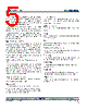
3 / 70 page  3 RT3606BE DS3606BE-04 June 2017 www.richtek.com © Copyright 2017 Richtek Technology Corporation. All rights reserved. is a registered trademark of Richtek Technology Corporation. Pin No Pin Name Pin Function 17 IMON CORE rail VR current monitor output. This pin outputs a voltage proportional to the loading current and a 1 resistor. 18 VREF Fixed 0.6V output reference voltage. This voltage is only used to offset the output voltage of IMON pin. Between this pin and GND must be placed a exact 0.47 F decoupling capacitor. 19 IMONA AXG rail VR current monitor output. This pin outputs a voltage proportional to the loading current. 20 VR_HOT Thermal monitor output, this pin is active low. 21 ALERT SVID alert. (Active low) 22 VDIO VR and CPU data transmission interface. 23 VCLK Synchronous Clock from the CPU. 24 EN VR enable control input. 25 OFSM Output voltage offset setting for CORE rail VR. 26 OFSA/PSYS Output voltage offset setting for AXG rail VR / System input power monitor. Place the PSYS resistor as close to the IC as possible. 27 VCC Controller power supply. Connect this pin to 5V and place a decoupling capacitor 2.2 F at least. The decoupling capacitor is placed as close VR controller as possible. 28 IBIAS Internal bias current setting. Connect a 100k resistor from this pin tied to GND to set the internal current. Don’t connect a bypass pass capacitor from this pin to GND. 29 RGNDA Return ground for AXG rail VR. This pin is the negative node of the differential remote voltage sensing. 30 VSENA AXG rail VR voltage sense input. This pin is connected to the terminal of AXG rail VR output voltage. 31 COMPA AXG rail VR compensation. This pin is the error amplifier output pin. 32 FBA Negative input of the error amplifier. This pin is for AXG rail VR output voltage feedback to controller. 35, 34 ISENA[1:2]P Positive current sense inputs of multi-phase AXG rail VR channel 1 and 2. 36, 33 ISENA[1:2]N Negative current sense inputs of multi-phase AXG rail VR channel 1 and 2. 37 TSENA Thermal sense input for AXG rail VR. 38 TONSETA AXG rail VR on-time setting. An on-time setting resistor is connected from this pin to input voltage. 39 DVD Divided input voltage detection of power stage. Connect this pin to a voltage divider from input voltage of power stage to detect input voltage. 40 PS4_Dr Dr.MOS enable control. Connecting to Dr.MOS PS4 function pin. As received PS4 command, this pin will be floating. If the Dr. MOS needs active low to enter PS4 or use discrete MOSFET, please reserve a 100k resistor to GND. 42, 41 PWMA[1:2] PWM output for AXG rail VR. 43 PS4 External driver enable control. Connecting to driver enable pin. As received PS4 command, this pin will be low state. 45, 44, 46 PWM[1:3] PWM outputs for CORE rail VR of channel 1, 2 and 3. 47 PGOOD VR ready indicator. 48 TONSET CORE rail VR on-time setting. An on-time setting resistor is connected from this pin to input voltage. 49 (Exposed Pad) GND Ground. The exposed pad must be soldered to a large PCB and connected to GND for maximum power dissipation. |
|
링크 URL |
| ALLDATASHEET 가 귀하에 도움이 되셨나요? [ DONATE ] |
Alldatasheet는? | 광고문의 | 운영자에게 연락하기 | 개인정보취급방침 | 링크 투 데이터시트 | 링크교환 | 제조사별 검색 All Rights Reserved©Alldatasheet.com |
| Russian : Alldatasheetru.com | Korean : Alldatasheet.co.kr | Spanish : Alldatasheet.es | French : Alldatasheet.fr | Italian : Alldatasheetit.com Portuguese : Alldatasheetpt.com | Polish : Alldatasheet.pl | Vietnamese : Alldatasheet.vn Indian : Alldatasheet.in | Mexican : Alldatasheet.com.mx | British : Alldatasheet.co.uk | New Zealand : Alldatasheet.co.nz |
|
Family Site : ic2ic.com |
icmetro.com |
 Korean ▼
 English
 Chinese
 German
 Japanese
 Russian
 Korean
 Spanish
 French
 Italian
 Portuguese
 Polish
 Vietnamese
 Indian
 Mexican
 British
 New Zealand