|
전자부품 데이터시트 검색엔진 |
|
|
전자부품 데이터시트 검색엔진 |
|
RI-RFM-006A 데이터시트(PDF) 15 Page - Texas Instruments |
|
|
|||||||||||||||||||||||||||||
RI-RFM-006A 데이터시트(HTML) 15 Page - Texas Instruments |
|
|
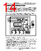
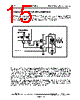
15 / 20 page  Rev. 3.5 RI-RFM-006A TIRIS RF-Module IC for Automotive Page 14 of 19 ! Typical Transmitter Circuit Configuration This RF-module IC is provided with “TXHI” and “TXLO” terminals which can drive external MOSFETs for driving the LC serial resonance antenna circuit. This resonance antenna circuit is to send 134.2-kHz signals to the remote TIRIS transponder. Use these terminals as illustrated below. In this circuit configuration, by selecting a value for R1 within a range of several hundred ohms and in accordance with the characteristics of MOSFETs (T1 and T2) and introducing the selected value, the through current which is consumed by the MOSFETs themselves during transmission can be reduced. If the value for R1 is too high, the on-state resistances of T1 and T2 become very high and they will have difficulty in driving the LC resonance circuit, leading to a possible reduction of available data communication distance. Therefore, it is recommended that the value for R1 be defined after careful evaluation of the characteristics of T1 and T2. L1 and C1 in the LC resonance circuit may be mutually exchanged in position without giving significant adverse effects to the operating performance of the circuit. However, the connection as is as illustrated above is most preferable since it reduces potential influence of high-voltage transmission signals produced at C1 on T1 and T2, thus a higher efficiency is gained. RI45538NS To receiving circuit R1 7 TXLO 8 TXHI LC resonance circuit GND VCC 134.2KHz C1 L1 T1 T2 Antenna |
|
|
링크 URL |
| ALLDATASHEET 가 귀하에 도움이 되셨나요? [ DONATE ] |
Alldatasheet는? | 광고문의 | 운영자에게 연락하기 | 개인정보취급방침 | 링크 투 데이터시트 | 링크교환 | 제조사별 검색 All Rights Reserved©Alldatasheet.com |
| Russian : Alldatasheetru.com | Korean : Alldatasheet.co.kr | Spanish : Alldatasheet.es | French : Alldatasheet.fr | Italian : Alldatasheetit.com Portuguese : Alldatasheetpt.com | Polish : Alldatasheet.pl | Vietnamese : Alldatasheet.vn Indian : Alldatasheet.in | Mexican : Alldatasheet.com.mx | British : Alldatasheet.co.uk | New Zealand : Alldatasheet.co.nz |
|
Family Site : ic2ic.com |
icmetro.com |
 Korean ▼
 English
 Chinese
 German
 Japanese
 Russian
 Korean
 Spanish
 French
 Italian
 Portuguese
 Polish
 Vietnamese
 Indian
 Mexican
 British
 New Zealand