|
전자부품 데이터시트 검색엔진 |
|
|
전자부품 데이터시트 검색엔진 |
|
ICS601-02 데이터시트(PDF) 3 Page - Integrated Circuit Systems |
|
|
|||||||||||||||||||||||||||||
ICS601-02 데이터시트(HTML) 3 Page - Integrated Circuit Systems |
|
|
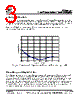
3 / 5 page  ICS601-02 Low Phase Noise Clock Multiplier MDS 601-02 D 3 Revision 111204 Integrated Circuit Systems, Inc. • 525 Race Street • San Jose • CA•95126 • (408) 295-9800tel • www.icst.com -140 -120 -100 -80 -60 -40 -20 0 10.0E+0 100.0E+0 1.0E+3 10.0E+3 100.0E+3 1.0E+6 10.0E+6 Offset from Carrier (Hz) Figure 1. Phase Noise of ICS601-02 at 125 MHz out, 25 MHz crystal input, VDD = 3.3 V. Figure 1 shows a typical phase noise measurement in a 125 MHz system. There are a few simple steps that can be taken to achieve these levels of phase noise from the ICS601-02. Variations in VDD will increase the phase noise, so it is important to have a stable, low noise supply voltage at the device. Use decoupling capacitors of 0.1 µF in parallel with 0.01 µF. It is important to have these capacitors as close as possible to the ICS601-02 supply pins. Disabling the REFOUT clock is also important for achieving low phase noise; lab tests have shown that this can reduce the phase noise by as much as 10 dBc/Hz. Achieving Low Phase Noise External Components/Crystal Selection The ICS601-02 requires a minimum number of external components for proper operation. Decoupling capacitors of 0.01 µF and 0.1 µF should be connected between VDD and GND, as close to the part as possible. A series termination resistor of 33 Ω may be used for the clock output. The crystal must be connected as close to the chip as possible. The crystal should be fundamental mode, parallel resonant. Do not use third overtone. For exact tuning when using a crystal, capacitors should be connected from pins X1 to ground and X2 to ground. In general, the value of these capacitors is given by the following equation, where CL is the crystal load capacitance: Crystal caps (pF) = (CL-5) x 2. So for a crystal with 16 pF load capacitance, two 22 pF caps can be used. For any given board layout, ICS can measure the board capacitance and recommend the exact capacitance value to use. |
|
|
링크 URL |
| ALLDATASHEET 가 귀하에 도움이 되셨나요? [ DONATE ] |
Alldatasheet는? | 광고문의 | 운영자에게 연락하기 | 개인정보취급방침 | 링크 투 데이터시트 | 링크교환 | 제조사별 검색 All Rights Reserved©Alldatasheet.com |
| Russian : Alldatasheetru.com | Korean : Alldatasheet.co.kr | Spanish : Alldatasheet.es | French : Alldatasheet.fr | Italian : Alldatasheetit.com Portuguese : Alldatasheetpt.com | Polish : Alldatasheet.pl | Vietnamese : Alldatasheet.vn Indian : Alldatasheet.in | Mexican : Alldatasheet.com.mx | British : Alldatasheet.co.uk | New Zealand : Alldatasheet.co.nz |
|
Family Site : ic2ic.com |
icmetro.com |
 Korean ▼
 English
 Chinese
 German
 Japanese
 Russian
 Korean
 Spanish
 French
 Italian
 Portuguese
 Polish
 Vietnamese
 Indian
 Mexican
 British
 New Zealand