|
전자부품 데이터시트 검색엔진 |
|
|
전자부품 데이터시트 검색엔진 |
|
7708 데이터시트(PDF) 18 Page - Power Integrations, Inc. |
|
|
|||||||||||||||||||||||||||||
7708 데이터시트(HTML) 18 Page - Power Integrations, Inc. |
|
|
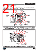
18 / 42 page  Rev. B 04/15 18 TFS7701-7708 www.power.com Figure 18. Proper Heat Sink, TFS-2, and PFC Connections to the Bulk Capacitor, are Necessary to Prevent Interference. PFC and HiperTFS-2 both need Dedicated Return Traces to Bulk Capacitor B-. Bulk Capacitor is PReferably Placed Between the PFC and HiperTFS-2. Figure 19. The (-) Terminal of the V AUX Capacitor Should be Connected to B- of the Bulk Capacitor, and not to the Ground Traces. This will Improve Lightning Surge and ESD Immunity, due to Capacitive Displacement Currents Flowing Through the Primary-to-Secondary Capacitance in the Flyback Transformer. PI-7014-053013 Bad Bulk Capacitor Standby Flyback VAUX Good Ok G S HiperTFS-2 Y Capacitor Connections Y class safety capacitors connected across the isolation barrier, should be routed directly to the positive of the bulk capacitor, and preferably to B+ instead of B- to divert surge and ESD currents away from the HiperTFS-2 small signal components and PCB traces. See Figure 20. PI-7029-053013 Bad Bad Ok Best B- Bulk Capacitor Heat Sink Foot Heat Sink S HiperTFS-2 S PFC This will also improve surge and ESD immunity. The secondary- side of the Y capacitor should be connected to the main transformer secondary return pin. This will reduce the height of thin “spikes” coincident with the main converter switching edges in the output ripple, which comes from common-mode switching noise. See Figure 21. |
|
링크 URL |
| ALLDATASHEET 가 귀하에 도움이 되셨나요? [ DONATE ] |
Alldatasheet는? | 광고문의 | 운영자에게 연락하기 | 개인정보취급방침 | 링크 투 데이터시트 | 링크교환 | 제조사별 검색 All Rights Reserved©Alldatasheet.com |
| Russian : Alldatasheetru.com | Korean : Alldatasheet.co.kr | Spanish : Alldatasheet.es | French : Alldatasheet.fr | Italian : Alldatasheetit.com Portuguese : Alldatasheetpt.com | Polish : Alldatasheet.pl | Vietnamese : Alldatasheet.vn Indian : Alldatasheet.in | Mexican : Alldatasheet.com.mx | British : Alldatasheet.co.uk | New Zealand : Alldatasheet.co.nz |
|
Family Site : ic2ic.com |
icmetro.com |
 Korean ▼
 English
 Chinese
 German
 Japanese
 Russian
 Korean
 Spanish
 French
 Italian
 Portuguese
 Polish
 Vietnamese
 Indian
 Mexican
 British
 New Zealand