|
전자부품 데이터시트 검색엔진 |
|
|
전자부품 데이터시트 검색엔진 |
|
L9965P 데이터시트(PDF) 85 Page - STMicroelectronics |
|
|
|||||||||||||||||||||||||||||
L9965P 데이터시트(HTML) 85 Page - STMicroelectronics |
|
|
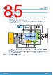
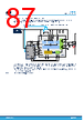
85 / 104 page  4 Application scenarios 4.1 Typical application circuit The application scenarios shown in the following are only for reference. Please refer to the dedicated Application Notes for more information. 4.1.1 12 V battery with MCU and ERBST mounted The Figure 29 shows a typical application diagram for a pyro-fuse system using the ERBST regulator and interfaced with a generic MCU. Figure 29. Application circuit: 12 V battery with MCU and ERBST mounted Arming logic Deployment driver 3V3 int regulator ER boost regulator ER discharge switch Global configuration and control, ADC, bias and diagnostics 5V or 3.3V PS FAULTN CWUP NCS SCLK SDI/MOSI SDO/MISO Power management, diagnostics and monitoring CIN LERBST DERBST CER1 RDCH VBAT PF PR PYRO FUSE VIO PGND TVS CER2 RFAULTN CVIO CPF CPR MCU CFAULTN MCU PMIC The CER electrolytic capacitors are connected to ERBST regulator that charges them to a higher voltage respect to battery level VBAT. ERDCHSW pin is used to allow CER controlled discharge for safety and diagnostic purposes. RDCHG sets the limit current for the discharge phase. Note: See the dedicated Application Note. L9965P Application scenarios DS14702 - Rev 4 page 85/104 |
|
링크 URL |
| ALLDATASHEET 가 귀하에 도움이 되셨나요? [ DONATE ] |
Alldatasheet는? | 광고문의 | 운영자에게 연락하기 | 개인정보취급방침 | 링크 투 데이터시트 | 링크교환 | 제조사별 검색 All Rights Reserved©Alldatasheet.com |
| Russian : Alldatasheetru.com | Korean : Alldatasheet.co.kr | Spanish : Alldatasheet.es | French : Alldatasheet.fr | Italian : Alldatasheetit.com Portuguese : Alldatasheetpt.com | Polish : Alldatasheet.pl | Vietnamese : Alldatasheet.vn Indian : Alldatasheet.in | Mexican : Alldatasheet.com.mx | British : Alldatasheet.co.uk | New Zealand : Alldatasheet.co.nz |
|
Family Site : ic2ic.com |
icmetro.com |
 Korean ▼
 English
 Chinese
 German
 Japanese
 Russian
 Korean
 Spanish
 French
 Italian
 Portuguese
 Polish
 Vietnamese
 Indian
 Mexican
 British
 New Zealand