|
전자부품 데이터시트 검색엔진 |
|
|
전자부품 데이터시트 검색엔진 |
|
EFS2ACD 데이터시트(PDF) 8 Page - STMicroelectronics |
|
|
|||||||||||||||||||||||||||||
EFS2ACD 데이터시트(HTML) 8 Page - STMicroelectronics |
|
|
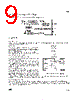
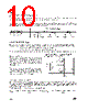
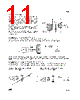
8 / 14 page  EFS 8/14 In order to reduce the number of components, an auxiliary power supply is integrated in the ASD ™. This active power supply works directly on the mains and requires only a low voltage capacitor 16V - 22 µF. The operating mode of this supply varies with the starter operating phase: 4/ AUXILIARY POWER SUPPLY: DRIVER ASD VCC G1 GND TUBE C SUPPLY 7.57 7.68 D1 R1 R2 R6 POWER SUPPLY SCHEMATIC Supply operation during preheat phase: During preheat phase, the driver manages alone the supply function (neither the driver nor D1 and R6 are involved). A part of the current flowing through the ASD ™ is used, at the beginning and at the end of each positive mains half cycle, to charge the output capacitor. Supply operation during standby phase: When the lamp is lit, the monitors its supply voltage (Vcc). At the beginning of each positive mains half cycle, when Vcc is lower than 7.57V, the driver closes the ASD ™ supply switch. The capacitor is charged to provide the standby current of the driver. During this phase the tube lamp is short circuited by the ASD ™. When the supply voltage reaches 7.68V, the driver opens the ASD™ supply switch. Since this current is also flowing in the ballast, the supply turn off provides across the lamp an additional voltage spike. After running few minutes the lamp becomes warm and this spike voltage naturally decreases. SUPPLY DURING PREHEAT PHASE Starter current Starter voltage at the ignition 5min after ignition SUPPLY DURING STANDBY PHASE (Without E.M.I. Capacitor nor R6 nor D1) To reduce dramatically this repetitive voltage spikes across the lamp, the R6 resistor with the diode D1 provide a part of the supply current. Thus, the ripple voltage of the supply voltage is reduced, as well as the level of the switched off current. On the other hand, this increases the safety margin of the RF noise (versus the IEC 55015 limits) |
|
|
링크 URL |
| ALLDATASHEET 가 귀하에 도움이 되셨나요? [ DONATE ] |
Alldatasheet는? | 광고문의 | 운영자에게 연락하기 | 개인정보취급방침 | 링크 투 데이터시트 | 링크교환 | 제조사별 검색 All Rights Reserved©Alldatasheet.com |
| Russian : Alldatasheetru.com | Korean : Alldatasheet.co.kr | Spanish : Alldatasheet.es | French : Alldatasheet.fr | Italian : Alldatasheetit.com Portuguese : Alldatasheetpt.com | Polish : Alldatasheet.pl | Vietnamese : Alldatasheet.vn Indian : Alldatasheet.in | Mexican : Alldatasheet.com.mx | British : Alldatasheet.co.uk | New Zealand : Alldatasheet.co.nz |
|
Family Site : ic2ic.com |
icmetro.com |
 Korean ▼
 English
 Chinese
 German
 Japanese
 Russian
 Korean
 Spanish
 French
 Italian
 Portuguese
 Polish
 Vietnamese
 Indian
 Mexican
 British
 New Zealand