|
전자부품 데이터시트 검색엔진 |
|
|
전자부품 데이터시트 검색엔진 |
|
EFS2ACD 데이터시트(PDF) 10 Page - STMicroelectronics |
|
|
|||||||||||||||||||||||||||||
EFS2ACD 데이터시트(HTML) 10 Page - STMicroelectronics |
|
|
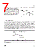
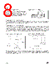
10 / 14 page  EFS 10/14 The driver determines the preheat duration by counting mains cycles. This numeric solution brings naturally a good precision depending only on the mains frequency tolerance. With the 2 driver versions, the EFS startlight-kit provides a choice of 4 preheat duration’s. The following table gives the preheat duration before the first ignition attempt. The seven next preheat duration’s, in case of unsuccessful ignition attempt, last the half of the first one 6/ PREHEAT PHASE DURATION 50-60Hz: PREHEAT DURATION MAINS FREQUENCY 50Hz 60Hz DRIVER VERSION EFS2A EFS2B EFS2B Pin 2 connection GND VCC GND VCC GND VCC 1.5s 2.56s 0.74s 1.24s 0.62s 1.03s During the ignition sequence or once the lamp is lit, the starter checks the state of the lamp (lit or off). To determine this state, the driver reads the lamp voltage through the resistor bridge (R1+R2+R3, R4). - If the lamp is off, its voltage equal the mains voltage. - If the lamp is lit, its voltage is only 80 V (for a 58W lamp). Thus the lamp state is determined by comparison of the lamp voltage with a programmed detection level. 7/ TUBE STATE DETECTION: DL DL TC min TC MAX min MAX LIT Lamp Voltage OFF Lamp Voltage CORRECT SETTING = NO WAVEFORM ACROSS THE GREY AREA Tolerance effects: Tolerances on resistors (R1, R2, R3 and R4) as well as on the integrated comparator bring a tolerance on the set detection level. Thus the detection level is included in a range delimited by the maximum and the minimum detection levels (DLMAX DLmin). The driver checks the state of the lamp when mains voltage is maximum, that is to say 5 ms after the zero crossing mains voltage (50Hz). Here again internal tolerances bring a tolerance on the real checking moment (TCmin TCMAX). How to set the detection level? Only the R4 resistor value can be set to adjust the detection level. Values of resitors R1 to R3 must match values of the table RECOMMENDED COMPONENTS ACCORDING TO APPLICATION CONDITIONS of the page 5. Practically the R4 resistor value has to be set so that neither the OFF lamp voltage nor the LIT lamp voltage cross the grey area. The DLMAX and DLmin limits can be calculated as follows: DL xR R R R R DL MAX MAX MAX MAX = ++ + 1265 4 1 2 3 4 .( ) and min min min = ++ + 1122 4 1 2 3 4 .( ) min min min xR R R R R MAX MAX |
|
|
링크 URL |
| ALLDATASHEET 가 귀하에 도움이 되셨나요? [ DONATE ] |
Alldatasheet는? | 광고문의 | 운영자에게 연락하기 | 개인정보취급방침 | 링크 투 데이터시트 | 링크교환 | 제조사별 검색 All Rights Reserved©Alldatasheet.com |
| Russian : Alldatasheetru.com | Korean : Alldatasheet.co.kr | Spanish : Alldatasheet.es | French : Alldatasheet.fr | Italian : Alldatasheetit.com Portuguese : Alldatasheetpt.com | Polish : Alldatasheet.pl | Vietnamese : Alldatasheet.vn Indian : Alldatasheet.in | Mexican : Alldatasheet.com.mx | British : Alldatasheet.co.uk | New Zealand : Alldatasheet.co.nz |
|
Family Site : ic2ic.com |
icmetro.com |
 Korean ▼
 English
 Chinese
 German
 Japanese
 Russian
 Korean
 Spanish
 French
 Italian
 Portuguese
 Polish
 Vietnamese
 Indian
 Mexican
 British
 New Zealand