|
전자부품 데이터시트 검색엔진 |
|
|
전자부품 데이터시트 검색엔진 |
|
H8SX/1663 데이터시트(PDF) 773 Page - Renesas Technology Corp |
|
|
|||||||||||||||||||||||||||||
H8SX/1663 데이터시트(HTML) 773 Page - Renesas Technology Corp |
|
|
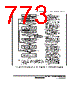
773 / 1158 page  Section 15 Serial Communication Interface (SCI, IrDA, CRC) Rev.1.00 Jun. 07, 2006 Page 721 of 1102 REJ09B0294-0100 Yes <End> [1] No Initialization Start transmission/reception [5] Error processing [3] Read receive data in RDR, and clear RDRF flag in SSR to 0 No Yes ORER = 1 All data received? [2] Read TDRE flag in SSR No Yes TDRE = 1 Write transmit data to TDR and clear TDRE flag in SSR to 0 No Yes RDRF = 1 Read ORER flag in SSR [4] Read RDRF flag in SSR Clear TE and RE bits in SCR to 0 [1] SCI initialization: The TxD pin is designated as the transmit data output pin, and the RxD pin is designated as the receive data input pin, enabling simultaneous transmit and receive operations. [2] SCI state check and transmit data write: Read SSR and check that the TDRE flag is set to 1, then write transmit data to TDR and clear the TDRE flag to 0. Transition of the TDRE flag from 0 to 1 can also be identified by a TXI interrupt. [3] Receive error processing: If a receive error occurs, read the ORER flag in SSR, and after performing the appropriate error processing, clear the ORER flag to 0. Reception cannot be resumed if the ORER flag is set to 1. [4] SCI state check and receive data read: Read SSR and check that the RDRF flag is set to 1, then read the receive data in RDR and clear the RDRF flag to 0. Transition of the RDRF flag from 0 to 1 can also be identified by an RXI interrupt. [5] Serial transmission/reception continuation procedure: To continue serial transmission/ reception, before the MSB (bit 7) of the current frame is received, finish reading the RDRF flag, reading RDR, and clearing the RDRF flag to 0. Also, before the MSB (bit 7) of the current frame is transmitted, read 1 from the TDRE flag to confirm that writing is possible. Then write data to TDR and clear the TDRE flag to 0. However, the TDRE flag is checked and cleared automatically when the DMAC or DTC is initiated by a transmit data empty interrupt (TXI) request and writes data to TDR. Similarly, the RDRF flag is cleared automatically when the DMAC or DTC is initiated by a receive data full interrupt (RXI) and reads data from RDR. Note: When switching from transmit or receive operation to simultaneous transmit and receive operations, first clear the TE bit and RE bit to 0, then set both these bits to 1 simultaneously. Figure 15.23 Sample Flowchart of Simultaneous Serial Transmission and Reception |
|
링크 URL |
| ALLDATASHEET 가 귀하에 도움이 되셨나요? [ DONATE ] |
Alldatasheet는? | 광고문의 | 운영자에게 연락하기 | 개인정보취급방침 | 링크 투 데이터시트 | 링크교환 | 제조사별 검색 All Rights Reserved©Alldatasheet.com |
| Russian : Alldatasheetru.com | Korean : Alldatasheet.co.kr | Spanish : Alldatasheet.es | French : Alldatasheet.fr | Italian : Alldatasheetit.com Portuguese : Alldatasheetpt.com | Polish : Alldatasheet.pl | Vietnamese : Alldatasheet.vn Indian : Alldatasheet.in | Mexican : Alldatasheet.com.mx | British : Alldatasheet.co.uk | New Zealand : Alldatasheet.co.nz |
|
Family Site : ic2ic.com |
icmetro.com |
 Korean ▼
 English
 Chinese
 German
 Japanese
 Russian
 Korean
 Spanish
 French
 Italian
 Portuguese
 Polish
 Vietnamese
 Indian
 Mexican
 British
 New Zealand