|
전자부품 데이터시트 검색엔진 |
|
|
전자부품 데이터시트 검색엔진 |
|
H8SX/1663 데이터시트(PDF) 962 Page - Renesas Technology Corp |
|
|
|||||||||||||||||||||||||||||
H8SX/1663 데이터시트(HTML) 962 Page - Renesas Technology Corp |
|
|
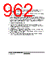
962 / 1158 page  Section 21 Flash Memory (0.18- µm F-ZTAT Version) Rev.1.00 Jun. 07, 2006 Page 910 of 1102 REJ09B0294-0100 1. After a transition to the USB boot mode is made, the boot program embedded in this LSI is initialized. This LSI performs enumeration to the host after the USB boot program is initialized. 2. Inquiry information about the size, configuration, start address, and support status of the user MAT is transmitted to the host. 3. After inquiries have finished, all user MAT are automatically erased. 4. After all user MAT are automatically erased, the state of waiting for programming/erasing command is entered. When the programming command is received, the state shifts to the state of waiting for programming data. The same applies to erasing. In addition to the commands for programming/erasing, there are commands for performing sum check, blank check (erasure check), and memory read of the user MAT, and acquiring the current status information. (3) Notes on USB Boot Mode Execution • The clock of 48 MHz needs to be supplied to the USB module. Set the external clock frequency and clock pulse generator so as to supply 48 MHz as the clock for the USB (cku). For details, refer to section 22, Clock Pulse Generator. • Use the PM4 pin for the D+ pull-up control connection. • For the stable supply of the power during the flash memory programming and erasing, the cable should not be connected via the bus powered HUB. • If the bus powered HUB is disconnected during the flash memory programming and erasing, permanent damage to the LSI may result. • If the USB bus in the bus power mode enters the suspend mode, this does not make the transition to the software standby mode in the power-down state. |
|
링크 URL |
| ALLDATASHEET 가 귀하에 도움이 되셨나요? [ DONATE ] |
Alldatasheet는? | 광고문의 | 운영자에게 연락하기 | 개인정보취급방침 | 링크 투 데이터시트 | 링크교환 | 제조사별 검색 All Rights Reserved©Alldatasheet.com |
| Russian : Alldatasheetru.com | Korean : Alldatasheet.co.kr | Spanish : Alldatasheet.es | French : Alldatasheet.fr | Italian : Alldatasheetit.com Portuguese : Alldatasheetpt.com | Polish : Alldatasheet.pl | Vietnamese : Alldatasheet.vn Indian : Alldatasheet.in | Mexican : Alldatasheet.com.mx | British : Alldatasheet.co.uk | New Zealand : Alldatasheet.co.nz |
|
Family Site : ic2ic.com |
icmetro.com |
 Korean ▼
 English
 Chinese
 German
 Japanese
 Russian
 Korean
 Spanish
 French
 Italian
 Portuguese
 Polish
 Vietnamese
 Indian
 Mexican
 British
 New Zealand