|
전자부품 데이터시트 검색엔진 |
|
|
전자부품 데이터시트 검색엔진 |
|
ADP1613ARMZ-R7 데이터시트(PDF) 5 Page - Analog Devices |
|
|
|||||||||||||||||||||||||||||
ADP1613ARMZ-R7 데이터시트(HTML) 5 Page - Analog Devices |
|
|
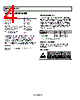
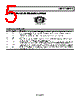
5 / 28 page  ADP1612/ADP1613 Rev. A | Page 5 of 28 PIN CONFIGURATION AND FUNCTION DESCRIPTIONS COMP 1 FB 2 EN 3 GND 4 SS 8 FREQ 7 VIN 6 SW 5 ADP1612/ ADP1613 TOP VIEW (Not to Scale) Figure 3. Pin Configuration Table 4. Pin Function Descriptions Pin No. Mnemonic Description 1 COMP Compensation Input. Connect a series resistor-capacitor network from COMP to GND to compensate the regulator. 2 FB Output Voltage Feedback Input. Connect a resistive voltage divider from the output voltage to FB to set the regulator output voltage. 3 EN Enable Input. Drive EN low to shut down the regulator; drive EN high to turn on the regulator. 4 GND Ground. 5 SW Switching Output. Connect the power inductor from the input voltage to SW and connect the external rectifier from SW to the output voltage to complete the step-up converter. 6 VIN Main Power Supply Input. VIN powers the ADP1612/ADP1613 internal circuitry. Connect VIN to the input source voltage. Bypass VIN to GND with a 10 μF or greater capacitor as close to the ADP1612/ADP1613 as possible. 7 FREQ Frequency Setting Input. FREQ controls the switching frequency. Connect FREQ to GND to program the oscillator to 650 kHz, or connect FREQ to VIN to program it to 1.3 MHz. If FREQ is left floating, the part defaults to 650 kHz. 8 SS Soft Start Timing Capacitor Input. A capacitor connected from SS to GND brings up the output slowly at power- up and reduces inrush current. |
|
|
링크 URL |
| ALLDATASHEET 가 귀하에 도움이 되셨나요? [ DONATE ] |
Alldatasheet는? | 광고문의 | 운영자에게 연락하기 | 개인정보취급방침 | 링크 투 데이터시트 | 링크교환 | 제조사별 검색 All Rights Reserved©Alldatasheet.com |
| Russian : Alldatasheetru.com | Korean : Alldatasheet.co.kr | Spanish : Alldatasheet.es | French : Alldatasheet.fr | Italian : Alldatasheetit.com Portuguese : Alldatasheetpt.com | Polish : Alldatasheet.pl | Vietnamese : Alldatasheet.vn Indian : Alldatasheet.in | Mexican : Alldatasheet.com.mx | British : Alldatasheet.co.uk | New Zealand : Alldatasheet.co.nz |
|
Family Site : ic2ic.com |
icmetro.com |
 Korean ▼
 English
 Chinese
 German
 Japanese
 Russian
 Korean
 Spanish
 French
 Italian
 Portuguese
 Polish
 Vietnamese
 Indian
 Mexican
 British
 New Zealand