|
전자부품 데이터시트 검색엔진 |
|
|
전자부품 데이터시트 검색엔진 |
|
POD3-R-DFS111 데이터시트(PDF) 4 Page - Hirose Electric |
|
|
|||||||||||||||||||||||||||||
POD3-R-DFS111 데이터시트(HTML) 4 Page - Hirose Electric |
|
|
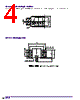
4 / 4 page  B26 sConnector Mounting Condition The mounting reference diagram is an anticipated diagram of the condition of mounting to a frame offset 0.3 mm from the card center line. sPCB mounting pattern PCB (7.5) (Ø 0.5 through hole) Corner escape portion Pad Copper foil portion (Resist layer beyond the pad) 1min 6 4 +0.1 +0 |
|
|
링크 URL |
| ALLDATASHEET 가 귀하에 도움이 되셨나요? [ DONATE ] |
Alldatasheet는? | 광고문의 | 운영자에게 연락하기 | 개인정보취급방침 | 링크 투 데이터시트 | 링크교환 | 제조사별 검색 All Rights Reserved©Alldatasheet.com |
| Russian : Alldatasheetru.com | Korean : Alldatasheet.co.kr | Spanish : Alldatasheet.es | French : Alldatasheet.fr | Italian : Alldatasheetit.com Portuguese : Alldatasheetpt.com | Polish : Alldatasheet.pl | Vietnamese : Alldatasheet.vn Indian : Alldatasheet.in | Mexican : Alldatasheet.com.mx | British : Alldatasheet.co.uk | New Zealand : Alldatasheet.co.nz |
|
Family Site : ic2ic.com |
icmetro.com |
 Korean ▼
 English
 Chinese
 German
 Japanese
 Russian
 Korean
 Spanish
 French
 Italian
 Portuguese
 Polish
 Vietnamese
 Indian
 Mexican
 British
 New Zealand