|
전자부품 데이터시트 검색엔진 |
|
|
전자부품 데이터시트 검색엔진 |
|
TS431BCX-RFG 데이터시트(PDF) 4 Page - Taiwan Semiconductor Company, Ltd |
|
|
|||||||||||||||||||||||||||||
TS431BCX-RFG 데이터시트(HTML) 4 Page - Taiwan Semiconductor Company, Ltd |
|
|
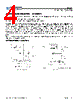
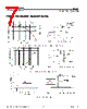
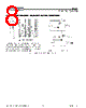
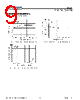
4 / 13 page  TS431 Taiwan Semiconductor Document Number: DS_P0000235 4 Version: H15 ADDITIONAL INFORMATION – STABILITY When The TS431/431A/431B is used as a shunt regulator, there are two options for selection of CL, are recommended for optional stability: A) No load capacitance across the device, decouple at the load. B) Large capacitance across the device, optional decoupling at the load. The reason for this is that TS431/431A/431B exhibits instability with capacitances in the range of 10nF to 1uF (approx.) at light cathode current up to 3mA (typ). The device is less stable the lower the cathode voltage has been set for. Therefore while the device will be perfectly stable operating at a cathode current of 10mA (approx.) with a 0.1uF capacitor across it, it will oscillate transiently during start up as the cathode current passes through the instability region. Select a very low capacitance, or alternatively a high capacitance (10uF) will avoid this issue altogether. Since the user will probably wish to have local decoupling at the load anyway, the most cost effective method is to use no capacitance at all directly across the device. PCB trace/via resistance and inductance prevent the local load decoupling from causing the oscillation during the transient start up phase. Note: if the TS431/431A/431B is located right at the load, so the load decoupling capacitor is directly across it, then this capacitor will have to be ≤1nF or ≥10uF. APPLICATIONS EXAMPLES Figure 1. Voltage Monitor Figure 2. Output Control for Three Terminal Fixed Regulator |
|
|
링크 URL |
| ALLDATASHEET 가 귀하에 도움이 되셨나요? [ DONATE ] |
Alldatasheet는? | 광고문의 | 운영자에게 연락하기 | 개인정보취급방침 | 링크 투 데이터시트 | 링크교환 | 제조사별 검색 All Rights Reserved©Alldatasheet.com |
| Russian : Alldatasheetru.com | Korean : Alldatasheet.co.kr | Spanish : Alldatasheet.es | French : Alldatasheet.fr | Italian : Alldatasheetit.com Portuguese : Alldatasheetpt.com | Polish : Alldatasheet.pl | Vietnamese : Alldatasheet.vn Indian : Alldatasheet.in | Mexican : Alldatasheet.com.mx | British : Alldatasheet.co.uk | New Zealand : Alldatasheet.co.nz |
|
Family Site : ic2ic.com |
icmetro.com |
 Korean ▼
 English
 Chinese
 German
 Japanese
 Russian
 Korean
 Spanish
 French
 Italian
 Portuguese
 Polish
 Vietnamese
 Indian
 Mexican
 British
 New Zealand