|
전자부품 데이터시트 검색엔진 |
|
|
전자부품 데이터시트 검색엔진 |
|
AND8067 데이터시트(PDF) 2 Page - ON Semiconductor |
|
|
|||||||||||||||||||||||||||||
AND8067 데이터시트(HTML) 2 Page - ON Semiconductor |
|
|
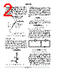
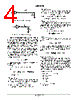
2 / 8 page  AND8067/D http://onsemi.com 2 Agilent Technologies HLMP subminiature LED lamps [3]. For example, the pulsed emerald green LED will have a light output approximately 30% brighter then the equivalent DC drive circuit at a peak pulsed current of 30 mA. Note that the pulsed circuit does not always produce a brighter LED. The pulsed emerald green LED has a brighter light output at peak currents greater than 10 mA; however, the DC circuit produces a brighter LED for peak currents less than 10 mA. Figure 2. LED Efficiency – Pulsed vs. DC Operation LED Drive Techniques DC Method Single LEDs are often driven using either a high side or low side switch. The conventional LED interface circuit consists of an open collector/drain driver to sink the LED current as shown in Figure 3. The brightness of the LED is proportional to the current (If) through the diode. The current through the LED for a current sinking configuration is calculated using VCC, Vf, R, and the voltage drop across the driver (VSwitch) as shown below. If + VCC * Vf * VSwitch R Figure 3. Conventional Open Collector DC LED Circuit VCC R LED ON/OFF If AC Method The second method to drive LEDs uses a pulsating square wave voltage. The suggested frequency and duty cycle varies for different LEDs; however, the typical frequency used is 1 kHz with a 10 to 30% duty cycle. Pulsing LEDs is the standard method used with multiplexed displays when a single driver circuit is interfaced to multiple LEDs. The current through a pulsed current sourcing driver such as the oscillator circuit shown in Figure 1 is calculated as shown below. If + VOH * Vf R Duty Cycle (current sourcing driver) The equation for a current sinking AC driver is similar to the DC method, except that the duty cycle is used to reduce the current consumption. If + VCC * Vf * VSwitch R Duty Cycle (current sinking driver) Dual Gate Inverter Oscillator Circuit The LED oscillator circuit, shown in Figure 1 is derived from the conventional two–inverter oscillator shown in Figure 4. The conventional oscillator is often denoted as an astable multivibrator and has a duty cycle of approximately 50%. In contrast, the LED oscillator circuit has two RC time constants so that both the duty cycle and frequency can be adjusted. R2 and C2 control the “ON” time of the LED pulse, while R1 and C1 control the “OFF” time. Figure 4. Conventional Inverter Oscillator U1A U1B R1 C1 R2 fOscillation ^ 1 2.3R1C1 (R2 + 10R1) The LED oscillator with the NL27WZ04 duel gate inverter and the given RC values is stable and does not have the oscillation start–up problem that often occurs with the conventional two inverter oscillator. In order to ensure oscillation at power–up, R4 was added in parallel with C2 to provide a DC path through the capacitor. The parallel impedance combination of R4 and C2 is effectively equal to the impedance of C2 at the oscillation frequency; therefore, R4 does not effect the oscillation frequency. The NL27WZ04 dual inverter is a standard buffered inverter that produces either a “high” (i.e. Vcc) or a “low” |
|
|
링크 URL |
| ALLDATASHEET 가 귀하에 도움이 되셨나요? [ DONATE ] |
Alldatasheet는? | 광고문의 | 운영자에게 연락하기 | 개인정보취급방침 | 링크 투 데이터시트 | 링크교환 | 제조사별 검색 All Rights Reserved©Alldatasheet.com |
| Russian : Alldatasheetru.com | Korean : Alldatasheet.co.kr | Spanish : Alldatasheet.es | French : Alldatasheet.fr | Italian : Alldatasheetit.com Portuguese : Alldatasheetpt.com | Polish : Alldatasheet.pl | Vietnamese : Alldatasheet.vn Indian : Alldatasheet.in | Mexican : Alldatasheet.com.mx | British : Alldatasheet.co.uk | New Zealand : Alldatasheet.co.nz |
|
Family Site : ic2ic.com |
icmetro.com |
 Korean ▼
 English
 Chinese
 German
 Japanese
 Russian
 Korean
 Spanish
 French
 Italian
 Portuguese
 Polish
 Vietnamese
 Indian
 Mexican
 British
 New Zealand