|
전자부품 데이터시트 검색엔진 |
|
|
전자부품 데이터시트 검색엔진 |
|
AND8067 데이터시트(PDF) 5 Page - ON Semiconductor |
|
|
|||||||||||||||||||||||||||||
AND8067 데이터시트(HTML) 5 Page - ON Semiconductor |
|
|
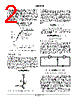
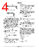
5 / 8 page  AND8067/D http://onsemi.com 5 Figure 10. DC LED Circuit with Normalized Current Equal to the Pulsed LED Oscillator of Figure 1 R5 680 Ω LED D2 VCC The oscillation and LED current measurements are summarized in Table 1. Figure 11 shows the PCB that was created to verify the operation of the LED circuits. The error in the calculated versus measure oscillation frequency is a result of the assumptions that VOH = VCC and VTH = 0.5 × VCC. In addition, the tolerance of the resistors and capacitors contributed to the frequency error. The pulsed LED is noticeably brighter than the DC LED; however, the LED’s light output was not quantified with a light spectrometer. Note that the maximum average current limit of the NL27WZ04 inverter is specified at 24 ma. The pulsed peak current exceeds the maximum limit; however, the current rating of the device is not exceeded because the average current is below the 24 ma limit. Although a maximum peak current limit is typically not specified for logic devices, a safe peak current can be verified by measuring the case temperature of the IC. If the temperature of the logic device is significantly higher than the ambient (i.e. 10–20 _C), the reliability of the circuit maybe reduced. The case temperature of the NL27WZ04 inverter of the LED oscillator did not significantly increase. Table 1. Experimental Results of the LED Oscillator VCC Calculated Oscillation Frequency Measured Oscillation Frequency Measured Duty Cycle Pulsed LED Peak Current Pulsed LED Average (RMS) Current DC LED Average Current 2.5 V 1.09 kHz 1.24 kHz 9.4% 9.79 mA 0.92 mA 0.98 mA 3.3 V 1.09 kHz 1.11 kHz 9.4% 21.3 mA 2.00 mA 2.06 mA 5.0 V 1.09 kHz 1.04 kHz 9.4% 46.7 mA 4.39 mA 4.45 mA Figure 11. LED Oscillator Evaluation PCB BIBLIOGRAPHY 1. “Application Note 1005: Operational Considerations for LED Lamps and Display Devices,” Agilent Technologies, 1999. 2. “Guidelines for Designs using LEDs: How to Enhance Display Performance without Increasing the Drive Current,” Fairchild Semiconductor, 1999. 3. HLMP–Pxxx, HLMP–Qxxx, HLMP–6xxx and HLMP–70xx Series Subminiature LED Lamps Datasheet, Agilent Technologies, 2000. 4. Smith, George, “Multiplexing LED Displays: Appnote 3,” Siemens Semiconductor. |
|
|
링크 URL |
| ALLDATASHEET 가 귀하에 도움이 되셨나요? [ DONATE ] |
Alldatasheet는? | 광고문의 | 운영자에게 연락하기 | 개인정보취급방침 | 링크 투 데이터시트 | 링크교환 | 제조사별 검색 All Rights Reserved©Alldatasheet.com |
| Russian : Alldatasheetru.com | Korean : Alldatasheet.co.kr | Spanish : Alldatasheet.es | French : Alldatasheet.fr | Italian : Alldatasheetit.com Portuguese : Alldatasheetpt.com | Polish : Alldatasheet.pl | Vietnamese : Alldatasheet.vn Indian : Alldatasheet.in | Mexican : Alldatasheet.com.mx | British : Alldatasheet.co.uk | New Zealand : Alldatasheet.co.nz |
|
Family Site : ic2ic.com |
icmetro.com |
 Korean ▼
 English
 Chinese
 German
 Japanese
 Russian
 Korean
 Spanish
 French
 Italian
 Portuguese
 Polish
 Vietnamese
 Indian
 Mexican
 British
 New Zealand