 |
전자부품 데이터시트 검색엔진 |
|
|
전자부품 데이터시트 검색엔진 |
|
The question interval is too short.
Please try again in a few seconds.

Hello, Please ask a question about M24M02-DR_V01 Datasheet
# Example questions:
➢ Explain the process of a 'sequential read' operation, including what actions the bus master must take to initiate and terminate it.
➢ What happens to the device's internal address counter after a successful read operation?
➢ What is the purpose of the ecc (error correction code) feature, and how does it function within the device?
| Part No. | M24M02-DR_V01 |
| Manufacturer | STMICROELECTRONICS |
| Size | 1,005 Kbytes |
| Pages | 40 pages |
| Description | 2-Mbit serial I²C bus EEPROM |



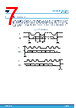


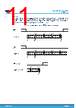



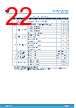

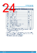


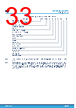
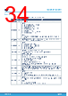





1. Addressing & Device Selection:
️· Device Type Identifier: The first byte sent in most communications (read/write) is a device select code. Crucially, the text specifies this code for different operations (see below).
️· Read/Write Bit: The most significant bit of the device select code designates read (RW=1) or write (RW=0) operation.
2. Write Operations
️· Standard Write: A standard I2C write sequence is used. The device accepts data and acknowledges (ACK).
️· ECC & Write Cycling: The EEPROM uses Error Correction Code (ECC). Writes operate on groups of 4 bytes, even if you only write a single byte. This is for data integrity. The total number of write cycles is limited per group of 4 bytes.
️· Write Delay/Polling: You can minimize wait times by polling the ACK signal after sending a write command. If no ACK is received, the device is still busy.
3. Read Operations
️· Random Address Read: Requires a "dummy" write sequence to load the desired address into the address counter *before* sending the read command.
️· Current Address Read: The EEPROM uses an internal address counter. This mode reads the byte at the current address in the counter. Note: Use with caution; it's better to use Random Address Read.
️· Sequential Read: After a successful read (current or random), you can keep the clock line high and acknowledge (ACK) the data to receive the next byte in sequence. Stop acknowledging (NACK) to end the sequence. The counter automatically increments.
️· Read Identification Page: Specific read operation for the separate Identification Page. Uses a modified device select code.
4. Identification Page (M24M02-DR only)
️· Dedicated Area: A separate 256-byte page for storing identification data.
️· Write Operations: Specific write and lock instructions for the identification page.
️· Locking: The identification page can be permanently locked in read-only mode for security.
5. Key Device Select Codes:
️· Standard Write: (Implied from context - likely the default device ID with RW=0).
️· Random Read/Write: Device Type Identifier + RW bit (RW = 1 for read, RW = 0 for write)
️· Identification Page Write: Device Type Identifier = 1011b
️· Lock Identification Page: Device Type Identifier = 1011b, Address Bit A10 = 1, Data = xxxx xx1x
️· Read Identification Page: Device Type Identifier = 1011b
6. Important Notes/Considerations:
️· Address Counter: The internal address counter is crucial for current address and sequential read operations.
️· Error Correction: ECC enhances data reliability, but it's important to understand its group-based operation.
️· Write Cycles: The total number of write cycles is limited per group of 4 bytes.
️· ACK/NACK: The acknowledgment (ACK) and non-acknowledgment (NACK) signals are critical for controlling the communication flow.
This summary should give you a good overview of how to communicate with the M24M02-DR/SO EEPROM using the I2C protocol. Let me know if you'd like me to elaborate on any specific aspect!
1. Addressing & Device Selection:
️· Device Type Identifier: The first byte sent in most communications (read/write) is a device select code. Crucially, the text specifies this code for different operations (see below).
️· Read/Write Bit: The most significant bit of the device select code designates read (RW=1) or write (RW=0) operation.
2. Write Operations
️· Standard Write: A standard I2C write sequence is used. The device accepts data and acknowledges (ACK).
️· ECC & Write Cycling: The EEPROM uses Error Correction Code (ECC). Writes operate on groups of 4 bytes, even if you only write a single byte. This is for data integrity. The total number of write cycles is limited per group of 4 bytes.
️· Write Delay/Polling: You can minimize wait times by polling the ACK signal after sending a write command. If no ACK is received, the device is still busy.
3. Read Operations
️· Random Address Read: Requires a "dummy" write sequence to load the desired address into the address counter *before* sending the read command.
️· Current Address Read: The EEPROM uses an internal address counter. This mode reads the byte at the current address in the counter. Note: Use with caution; it's better to use Random Address Read.
️· Sequential Read: After a successful read (current or random), you can keep the clock line high and acknowledge (ACK) the data to receive the next byte in sequence. Stop acknowledging (NACK) to end the sequence. The counter automatically increments.
️· Read Identification Page: Specific read operation for the separate Identification Page. Uses a modified device select code.
4. Identification Page (M24M02-DR only)
️· Dedicated Area: A separate 256-byte page for storing identification data.
️· Write Operations: Specific write and lock instructions for the identification page.
️· Locking: The identification page can be permanently locked in read-only mode for security.
5. Key Device Select Codes:
️· Standard Write: (Implied from context - likely the default device ID with RW=0).
️· Random Read/Write: Device Type Identifier + RW bit (RW = 1 for read, RW = 0 for write)
️· Identification Page Write: Device Type Identifier = 1011b
️· Lock Identification Page: Device Type Identifier = 1011b, Address Bit A10 = 1, Data = xxxx xx1x
️· Read Identification Page: Device Type Identifier = 1011b
6. Important Notes/Considerations:
️· Address Counter: The internal address counter is crucial for current address and sequential read operations.
️· Error Correction: ECC enhances data reliability, but it's important to understand its group-based operation.
️· Write Cycles: The total number of write cycles is limited per group of 4 bytes.
️· ACK/NACK: The acknowledgment (ACK) and non-acknowledgment (NACK) signals are critical for controlling the communication flow.
This summary should give you a good overview of how to communicate with the M24M02-DR/SO EEPROM using the I2C protocol. Let me know if you'd like me to elaborate on any specific aspect!
| Part No. | M24M02-DR_V01 |
| Manufacturer | STMICROELECTRONICS |
| Size | 1,005 Kbytes |
| Pages | 40 pages |
| Description | 2-Mbit serial I²C bus EEPROM |
| ALLDATASHEET 가 귀하에 도움이 되셨나요? [ DONATE ] |
Alldatasheet는? | 광고문의 | 운영자에게 연락하기 | 개인정보취급방침 | 링크 투 데이터시트 | 링크교환 | 제조사별 검색 All Rights Reserved©Alldatasheet.com |
| Russian : Alldatasheetru.com | Korean : Alldatasheet.co.kr | Spanish : Alldatasheet.es | French : Alldatasheet.fr | Italian : Alldatasheetit.com Portuguese : Alldatasheetpt.com | Polish : Alldatasheet.pl | Vietnamese : Alldatasheet.vn Indian : Alldatasheet.in | Mexican : Alldatasheet.com.mx | British : Alldatasheet.co.uk | New Zealand : Alldatasheet.co.nz |
|
Family Site : ic2ic.com |
icmetro.com |
 Korean ▼
  English
 Chinese
 German
 Japanese
 Russian
 Spanish
 French
 Italian
 Portuguese
 Polish
 Vietnamese
 Indian
 Mexican
 British
 New Zealand