 |
전자부품 데이터시트 검색엔진 |
|
|
전자부품 데이터시트 검색엔진 |
|
The question interval is too short.
Please try again in a few seconds.

Hello, Please ask a question about AS3930_07 Datasheet
# Example questions:
➢ What are the three main operating modes of the as3930, and what is the typical current consumption in power down mode?
➢ How does the on/off mode function, and what register controls the duty cycle in this mode?
➢ What is the purpose of the 'artificial wake-up' feature, and how can the period of this feature be defined?
| Part No. | AS3930_07 |
| Manufacturer | AMSCO |
| Size | 491 Kbytes |
| Pages | 32 pages |
| Description | Single Channel Low Frequency Wakeup Receiver |












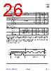
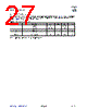


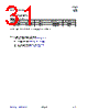


1. Overview: What is the AS3930?
️· The AS3930 is a low-power, digitally controlled FM receiver designed primarily for remote control applications. Think of things like key fobs, garage door openers, weather stations, or any application needing to receive low-frequency (LF) signals.
️· It's characterized by its flexibility in operating modes and digital control, allowing for fine-tuning of its performance.
2. Operating Modes
️· Power Down Mode: Complete shutdown, extremely low current consumption (400 nA).
️· Listening Mode: The receiver is active, detecting a carrier signal. This has two sub-modes:
- Standard Listening Mode: Continuous channel amplification.
- ON/OFF Mode (Low Power Mode): Amplifier is active for a short time (programmable), then turned off, saving power.
️· Preamble Detection/Pattern Correlation: This mode is crucial for applications requiring recognition of a specific coded signal (like in a remote control). The receiver looks for a preamble (initial frequency burst) and then compares the received data pattern against a pre-programmed pattern. A match triggers a wake-up interrupt.
️· Data Receiving: After a successful preamble/pattern match, the receiver can operate as a normal OOK (On-Off Keying) receiver, retrieving data. A timeout feature can automatically return the receiver to listening mode.
3. Key Features & Functions
️· Digital Control: Many parameters of the receiver are controlled through registers, allowing for customization.
️· AGC (Automatic Gain Control): Automatically adjusts the receiver's gain to maintain a consistent signal level.
️· RSSI (Received Signal Strength Indicator): Provides an indication of the signal strength.
️· Programmable Wake-up: Allows for artificially generating a wake-up interrupt, useful for periodic checks or environmental sensing.
️· Artificial Wake-up Interrupt: Lasts only 128µs, helping to distinguish it from a true signal detection interrupt.
️· Data Correlation: Allows the receiver to recognize specific signal patterns.
️· Crystal Oscillator / Internal RC Oscillator: Can operate with an external crystal oscillator for higher precision or an internal RC oscillator for simplicity (and lower component count). If using the internal RC oscillator, specific pins must be configured.
4. Registers (Key Highlights)
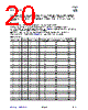
The datasheet provides a table listing the registers and their functions. Some of the most important ones:
️· R0: Controls Power Down and ON/OFF operation mode.
️· R1: Enables functions like AGC, Antenna Damper, Data Correlation and Crystal oscillator
️· R4: Controls OFF-time in the ON/OFF mode.
️· R7: Defines timeout periods and H-bit timing parameters.
️· R8: Sets parameters for the Artificial Wake-up function.
5. Pin Configuration Notes (for Internal RC operation)
️· If you're using the internal RC oscillator instead of a crystal, specific pin configurations are required:
- Pin XIN must be connected to the supply voltage.
- Pin XOUT must be left floating.
6. Application Diagram
️· The receiver can be implemented using an external LC resonator or a crystal oscillator.
1. Overview: What is the AS3930?
️· The AS3930 is a low-power, digitally controlled FM receiver designed primarily for remote control applications. Think of things like key fobs, garage door openers, weather stations, or any application needing to receive low-frequency (LF) signals.
️· It's characterized by its flexibility in operating modes and digital control, allowing for fine-tuning of its performance.
2. Operating Modes
️· Power Down Mode: Complete shutdown, extremely low current consumption (400 nA).
️· Listening Mode: The receiver is active, detecting a carrier signal. This has two sub-modes:
- Standard Listening Mode: Continuous channel amplification.
- ON/OFF Mode (Low Power Mode): Amplifier is active for a short time (programmable), then turned off, saving power.
️· Preamble Detection/Pattern Correlation: This mode is crucial for applications requiring recognition of a specific coded signal (like in a remote control). The receiver looks for a preamble (initial frequency burst) and then compares the received data pattern against a pre-programmed pattern. A match triggers a wake-up interrupt.
️· Data Receiving: After a successful preamble/pattern match, the receiver can operate as a normal OOK (On-Off Keying) receiver, retrieving data. A timeout feature can automatically return the receiver to listening mode.
3. Key Features & Functions
️· Digital Control: Many parameters of the receiver are controlled through registers, allowing for customization.
️· AGC (Automatic Gain Control): Automatically adjusts the receiver's gain to maintain a consistent signal level.
️· RSSI (Received Signal Strength Indicator): Provides an indication of the signal strength.
️· Programmable Wake-up: Allows for artificially generating a wake-up interrupt, useful for periodic checks or environmental sensing.
️· Artificial Wake-up Interrupt: Lasts only 128µs, helping to distinguish it from a true signal detection interrupt.
️· Data Correlation: Allows the receiver to recognize specific signal patterns.
️· Crystal Oscillator / Internal RC Oscillator: Can operate with an external crystal oscillator for higher precision or an internal RC oscillator for simplicity (and lower component count). If using the internal RC oscillator, specific pins must be configured.
4. Registers (Key Highlights)
The datasheet provides a table listing the registers and their functions. Some of the most important ones:
️· R0: Controls Power Down and ON/OFF operation mode.
️· R1: Enables functions like AGC, Antenna Damper, Data Correlation and Crystal oscillator
️· R4: Controls OFF-time in the ON/OFF mode.
️· R7: Defines timeout periods and H-bit timing parameters.
️· R8: Sets parameters for the Artificial Wake-up function.
5. Pin Configuration Notes (for Internal RC operation)
️· If you're using the internal RC oscillator instead of a crystal, specific pin configurations are required:
- Pin XIN must be connected to the supply voltage.
- Pin XOUT must be left floating.
6. Application Diagram
️· The receiver can be implemented using an external LC resonator or a crystal oscillator.
| Part No. | AS3930_07 |
| Manufacturer | AMSCO |
| Size | 491 Kbytes |
| Pages | 32 pages |
| Description | Single Channel Low Frequency Wakeup Receiver |
| ALLDATASHEET 가 귀하에 도움이 되셨나요? [ DONATE ] |
Alldatasheet는? | 광고문의 | 운영자에게 연락하기 | 개인정보취급방침 | 링크 투 데이터시트 | 링크교환 | 제조사별 검색 All Rights Reserved©Alldatasheet.com |
| Russian : Alldatasheetru.com | Korean : Alldatasheet.co.kr | Spanish : Alldatasheet.es | French : Alldatasheet.fr | Italian : Alldatasheetit.com Portuguese : Alldatasheetpt.com | Polish : Alldatasheet.pl | Vietnamese : Alldatasheet.vn Indian : Alldatasheet.in | Mexican : Alldatasheet.com.mx | British : Alldatasheet.co.uk | New Zealand : Alldatasheet.co.nz |
|
Family Site : ic2ic.com |
icmetro.com |
 Korean ▼
  English
 Chinese
 German
 Japanese
 Russian
 Spanish
 French
 Italian
 Portuguese
 Polish
 Vietnamese
 Indian
 Mexican
 British
 New Zealand