|
전자부품 데이터시트 검색엔진 |
|
|
전자부품 데이터시트 검색엔진 |
|
DS31256 데이터시트(PDF) 69 Page - Maxim Integrated Products |
|
|
|||||||||||||||||||||||||||||
DS31256 데이터시트(HTML) 69 Page - Maxim Integrated Products |
|
|
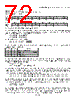
69 / 183 page  DS31256 256-Channel, High-Throughput HDLC Controller 69 of 183 7.2 HDLC Register Description Register Name: RHCDIS Register Description: Receive HDLC Channel Definition Indirect Select Register Address: 0400h Bit # 7 6 5 4 3 2 1 0 Name HCID7 HCID6 HCID5 HCID4 HCID3 HCID2 HCID1 HCID0 Default 0 0 0 0 0 0 0 0 Bit # 15 14 13 12 11 10 9 8 Name IAB IARW n/a n/a n/a n/a n/a n/a Default 0 0 0 0 0 0 0 0 Note: Bits that are underlined are read-only; all other bits are read-write. Bits 0 to 7/HDLC Channel ID (HCID0 to HCID7) 00000000 (00h) = HDLC channel number 1 (also used for the fast HDLC engine on port 0) 00000001 (01h) = HDLC channel number 2 (also used for the fast HDLC engine on port 1) 00000010 (02h) = HDLC channel number 3 (also used for the fast HDLC engine on port 2) 00000011 (03h) = HDLC channel number 4 11111111 (FFh) = HDLC channel number 256 Bit 14/Indirect Access Read/Write (IARW). When the host wishes to read data from the internal receive HDLC definition RAM, the host should write this bit to 1. This causes the device to begin obtaining the data from the channel location indicated by the HCID bits. During the read access, the IAB bit is set to 1. Once the data is ready to be read from the RHCD register, the IAB bit is set to 0. When the host wishes to write data to the internal receive HDLC definition RAM, the host should write this bit to 0. This causes the device to take the data that is currently present in the RHCD register and write it to the channel location indicated by the HCID bits. When the device completes the write, the IAB is set to 0. Bit 15/Indirect Access Busy (IAB). When an indirect read or write access is in progress, this read-only bit is set to 1. During a read operation, this bit sets to 1 until the data is ready to be read. It is set to 0 when the data is ready to be read. During a write operation, this bit is set to 1 while the write is taking place. It is set to 0 once the write operation completes. Register Name: RHCD Register Description: Receive HDLC Channel Definition Register Address: 0404h Bit # 7 6 5 4 3 2 1 0 Name RABTD RCS RBF RID RCRC1 RCRC0 ROLD RTRANS Default 0 0 0 0 0 0 0 0 Bit # 15 14 13 12 11 10 9 8 Name n/a n/a n/a n/a n/a n/a n/a RZDD Default 0 0 0 0 0 0 0 0 Note: Bits that are underlined are read-only; all other bits are read-write. Bit 0/Receive Transparent Enable (RTRANS). When this bit is set low, the HDLC controller performs flag delineation, zero destuffing, abort detection, octet length checking (if enabled through ROLD), and FCS checking (if enabled through RCRC0/1). When this bit is set high, the HDLC controller does not perform flag delineation, |
|
링크 URL |
| ALLDATASHEET 가 귀하에 도움이 되셨나요? [ DONATE ] |
Alldatasheet는? | 광고문의 | 운영자에게 연락하기 | 개인정보취급방침 | 링크 투 데이터시트 | 링크교환 | 제조사별 검색 All Rights Reserved©Alldatasheet.com |
| Russian : Alldatasheetru.com | Korean : Alldatasheet.co.kr | Spanish : Alldatasheet.es | French : Alldatasheet.fr | Italian : Alldatasheetit.com Portuguese : Alldatasheetpt.com | Polish : Alldatasheet.pl | Vietnamese : Alldatasheet.vn Indian : Alldatasheet.in | Mexican : Alldatasheet.com.mx | British : Alldatasheet.co.uk | New Zealand : Alldatasheet.co.nz |
|
Family Site : ic2ic.com |
icmetro.com |
 Korean ▼
 English
 Chinese
 German
 Japanese
 Russian
 Korean
 Spanish
 French
 Italian
 Portuguese
 Polish
 Vietnamese
 Indian
 Mexican
 British
 New Zealand