|
전자부품 데이터시트 검색엔진 |
|
|
전자부품 데이터시트 검색엔진 |
|
LM393DGKR 데이터시트(PDF) 15 Page - Texas Instruments |
|
|
|
|||||||||||||||||||||||||||||
LM393DGKR 데이터시트(HTML) 15 Page - Texas Instruments |
|
|
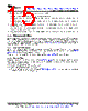
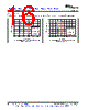
15 / 40 page  15 LM193, LM293, LM293A, LM393, LM393A, LM2903, LM2903V, LM393B, LM2903B www.ti.com SLCS005AA – OCTOBER 1979 – REVISED SEPTEMBER 2019 Product Folder Links: LM193 LM293 LM293A LM393 LM393A LM2903 LM2903V LM393B LM2903B Submit Documentation Feedback Copyright © 1979–2019, Texas Instruments Incorporated The following is a list of input voltage situation and their outcomes: 1. When both IN- and IN+ are both within the common-mode range: a. If IN- is higher than IN+ and the offset voltage, the output is low and the output transistor is sinking current b. If IN- is lower than IN+ and the offset voltage, the output is high impedance and the output transistor is not conducting 2. When IN- is higher than common-mode and IN+ is within common-mode, the output is low and the output transistor is sinking current 3. When IN+ is higher than common-mode and IN- is within common-mode, the output is high impedance and the output transistor is not conducting 4. When IN- and IN+ are both higher than common-mode, the output is low and the output transistor is sinking current 8.2.2.2 Minimum Overdrive Voltage Overdrive Voltage is the differential voltage produced between the positive and negative inputs of the comparator over the offset voltage (VIO). To make an accurate comparison the Overdrive Voltage (VOD) should be higher than the input offset voltage (VIO). Overdrive voltage can also determine the response time of the comparator, with the response time decreasing with increasing overdrive. Figure 8 and Figure 9 show positive and negative response times with respect to overdrive voltage. 8.2.2.3 Output and Drive Current Output current is determined by the load/pull-up resistance and logic/pullup voltage. The output current produces a output low voltage (VOL) from the comparator. In which VOL is proportional to the output current. Use Typical Characteristics to determine VOL based on the output current. The output current can also effect the transient response. See Response Time for more information. 8.2.2.4 Response Time Response time is a function of input over drive. See Application Curves for typical response times. The rise and falls times can be determined by the load capacitance (CL), load/pullup resistance (RPULLUP) and equivalent collector-emitter resistance (RCE). • The rise time (τR) is approximately τR ~ RPULLUP × CL • The fall time (τF) is approximately τF ~ RCE × CL – RCE can be determine by taking the slope of Typical Characteristics in its linear region at the desired temperature, or by dividing the VOL by Iout |
|
링크 URL |
| ALLDATASHEET 가 귀하에 도움이 되셨나요? [ DONATE ] |
Alldatasheet는? | 광고문의 | 운영자에게 연락하기 | 개인정보취급방침 | 링크 투 데이터시트 | 링크교환 | 제조사별 검색 All Rights Reserved©Alldatasheet.com |
| Russian : Alldatasheetru.com | Korean : Alldatasheet.co.kr | Spanish : Alldatasheet.es | French : Alldatasheet.fr | Italian : Alldatasheetit.com Portuguese : Alldatasheetpt.com | Polish : Alldatasheet.pl | Vietnamese : Alldatasheet.vn Indian : Alldatasheet.in | Mexican : Alldatasheet.com.mx | British : Alldatasheet.co.uk | New Zealand : Alldatasheet.co.nz |
|
Family Site : ic2ic.com |
icmetro.com |
 Korean ▼
 English
 Chinese
 German
 Japanese
 Russian
 Korean
 Spanish
 French
 Italian
 Portuguese
 Polish
 Vietnamese
 Indian
 Mexican
 British
 New Zealand