|
전자부품 데이터시트 검색엔진 |
|
|
전자부품 데이터시트 검색엔진 |
|
STM32U545NET3QTR 데이터시트(PDF) 23 Page - STMicroelectronics |
|
|
|||||||||||||||||||||||||||||
STM32U545NET3QTR 데이터시트(HTML) 23 Page - STMicroelectronics |
|
|
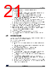
23 / 283 page  DS14216 Rev 1 23/283 STM32U545xx Functional overview 88 3.4.1 Flash memory protection The option bytes allow the configuration of flexible protections: • write protection (WRP) to protect areas against erasing and programming. Two areas per bank can be selected with 8-Kbyte granularity. • RDP (readout protection) to protect the whole memory, has four levels of protection available (see Table 3 and Table 4): – Level 0: no readout protection – Level 0.5: available only when TrustZone is enabled All read/write operations (if no write protection is set) from/to the nonsecure flash memory are possible. The debug access to secure area is prohibited. Debug access to nonsecure area remains possible. – Level 1: memory readout protection The flash memory cannot be read from or written to if either the debug features are connected or the boot in RAM or bootloader are selected. If TrustZone is enabled, the nonsecure debug is possible and the boot in SRAM is not possible. Regressions from Level 1 to lower levels can be protected by password authentication. – Level 2: chip readout protection The debug features, the boot in RAM and the bootloader selection are disabled. A secure secret key can be configured in the secure options to allow the regression capability from Level 2 to Level 1. By default (key not configured), this Level 2 selection is irreversible and JTAG/SWD interfaces are disabled. If the secret key was previously configured in lower RDP levels, the device enables the RDP regression from Level 2 to Level 1 after password authentication through JTAG/SWD interface. Note: In order to reach the best protection level, it is recommended to activate TrustZone and to set the RDP Level 2 with password authentication regression enabled. Table 3. Access status versus protection level and execution modes when TZEN = 0 Area RDP level User execution (boot from flash memory) Debug/boot from RAM/ bootloader(1) Read Write Erase Read Write Erase Flash main memory 1 Yes Yes Yes No No No(4) 2 Yes Yes Yes N/A N/A N/A System memory (2) 1 Yes No No Yes No No 2 Yes No No N/A N/A N/A Option bytes(3) 1Yes Yes(4) N/A Yes Yes(4) N/A 2Yes No(5) N/A N/A N/A N/A OTP 1Yes Yes(6) N/A Yes Yes(6) N/A 2Yes Yes(6) N/A N/A N/A N/A |
|
링크 URL |
| ALLDATASHEET 가 귀하에 도움이 되셨나요? [ DONATE ] |
Alldatasheet는? | 광고문의 | 운영자에게 연락하기 | 개인정보취급방침 | 링크 투 데이터시트 | 링크교환 | 제조사별 검색 All Rights Reserved©Alldatasheet.com |
| Russian : Alldatasheetru.com | Korean : Alldatasheet.co.kr | Spanish : Alldatasheet.es | French : Alldatasheet.fr | Italian : Alldatasheetit.com Portuguese : Alldatasheetpt.com | Polish : Alldatasheet.pl | Vietnamese : Alldatasheet.vn Indian : Alldatasheet.in | Mexican : Alldatasheet.com.mx | British : Alldatasheet.co.uk | New Zealand : Alldatasheet.co.nz |
|
Family Site : ic2ic.com |
icmetro.com |
 Korean ▼
 English
 Chinese
 German
 Japanese
 Russian
 Korean
 Spanish
 French
 Italian
 Portuguese
 Polish
 Vietnamese
 Indian
 Mexican
 British
 New Zealand