|
전자부품 데이터시트 검색엔진 |
|
|
전자부품 데이터시트 검색엔진 |
|
E5CD-RX2DBM-002 데이터시트(PDF) 48 Page - Omron Electronics LLC |
|
|
|||||||||||||||||||||||||||||
E5CD-RX2DBM-002 데이터시트(HTML) 48 Page - Omron Electronics LLC |
|
|
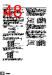
48 / 56 page  E5CD/E5ED 48 Precautions when Wiring • Separate input leads and power lines in order to prevent external noise. • Use crimp terminals when wiring the screw terminals. • Use the suitable wiring material and crimp tools for crimp terminals. • Tighten the terminal screws to a torque of 0.43 to 0.58 N·m. E5CD/E5ED (Screw Terminal Blocks) Wires Use the wire specifications given in the following table. • Strip the wires on which crimp terminals will be used to the length recommended by the crimp terminal manufacturer. • Use shielded twisted-pair cables for signal lines to prevent the influence of noise. Crimp Terminals For the E5CD or E5ED, use the following types of crimp terminals for M3 screws. Although you can connect two crimp terminals with insulation sleeves to one terminal, you cannot do so if the diameter of the insulation sleeves is too large. E5 @D-B (Push-In Plus terminal block types) 1. Connecting Wires to Push-In Plus Terminal Block Part Names of the Terminal Block Connecting Wires with Ferrules and Solid Wires Insert the solid wire or ferrule straight into the terminal block until the end strikes the terminal block. If a wire is difficult to connect because it is too thin, use a flat-blade screwdriver in the same way as when connecting stranded wire. Connecting Stranded Wires Use the following procedure to connect the wires to the terminal block. 1. Hold a flat-blade screwdriver at an angle and insert it into the release hole. The angle should be between 10° and 15°. If the flat- blade screwdriver is inserted correctly, you will feel the spring in the release hole. 2. With the screwdriver still inserted into the release hole, insert the wire into the terminal hole until it strikes the terminal block. 3. Remove the flat-blade screwdriver from the release hole. Checking Connections • After the insertion, pull gently on the wire to make sure that it will not come off and the wire is securely fastened to the terminal block. • If you use a ferrule with a conductor length of 10 mm, part of the conductor may be visible after the ferrule is inserted into the terminal block, but the product insulation distance will still be satisfied. 2. Removing Wires from Push-In Plus Terminal Block Use the following procedure to remove wires from the terminal block. The same method is used to remove stranded wires, solid wires, and ferrules. 1. Hold a flat-blade screwdriver at an angle and insert it into the release hole. 2. With the screwdriver still inserted into the release hole, remove the wire from the terminal insertion hole. 3. Remove the flat-blade screwdriver from the release hole. Model Recommended wires Stripping length E5CD or E5ED AWG24 to AWG18 (0.205 to 0.823 mm2) 6 to 8 mm (when crimp terminals are not used) 5.8 mm max. 5.8 mm max. Terminal (Insertion) hole Release hole Ferrules and Solid Wires (1) (2) (3) Flat-blade screwdriver 10 to 15° (1) (2) (3) Flat-blade screwdriver 10 to 15° |
|
링크 URL |
| ALLDATASHEET 가 귀하에 도움이 되셨나요? [ DONATE ] |
Alldatasheet는? | 광고문의 | 운영자에게 연락하기 | 개인정보취급방침 | 링크 투 데이터시트 | 링크교환 | 제조사별 검색 All Rights Reserved©Alldatasheet.com |
| Russian : Alldatasheetru.com | Korean : Alldatasheet.co.kr | Spanish : Alldatasheet.es | French : Alldatasheet.fr | Italian : Alldatasheetit.com Portuguese : Alldatasheetpt.com | Polish : Alldatasheet.pl | Vietnamese : Alldatasheet.vn Indian : Alldatasheet.in | Mexican : Alldatasheet.com.mx | British : Alldatasheet.co.uk | New Zealand : Alldatasheet.co.nz |
|
Family Site : ic2ic.com |
icmetro.com |
 Korean ▼
 English
 Chinese
 German
 Japanese
 Russian
 Korean
 Spanish
 French
 Italian
 Portuguese
 Polish
 Vietnamese
 Indian
 Mexican
 British
 New Zealand