|
전자부품 데이터시트 검색엔진 |
|
|
전자부품 데이터시트 검색엔진 |
|
AT80C51RA2-RLSIV 데이터시트(PDF) 55 Page - ATMEL Corporation |
|
|
|||||||||||||||||||||||||||||
AT80C51RA2-RLSIV 데이터시트(HTML) 55 Page - ATMEL Corporation |
|
|
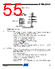
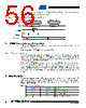
55 / 86 page  55 4188F–8051–01/08 AT/TS8xC51Rx2 Figure 9-1. Set-Up Modes Configuration 9.3.3 Programming Algorithm The Improved Quick Pulse algorithm is based on the Quick Pulse algorithm and decreases the number of pulses applied during byte programming from 25 to 1. To program the TS87C51RB2/RC2/RD2 the following sequence must be exercised: • Step 1: Activate the combination of control signals. • Step 2: Input the valid address on the address lines. • Step 3: Input the appropriate data on the data lines. • Step 4: Raise EA/VPP from VCC to VPP (typical 12.75V). • Step 5: Pulse ALE/PROG once. • Step 6: Lower EA/VPP from VPP to VCC Repeat step 2 through 6 changing the address and data for the entire array or until the end of the object file is reached (See Figure 9-2). 9.3.4 Verify algorithm Code array verify must be done after each byte or block of bytes is programmed. In either case, a complete verify of the programmed array will ensure reliable programming of the TS87C51RB2/RC2/RD2. P 2.7 is used to enable data output. To verify the TS87C51RB2/RC2/RD2 code the following sequence must be exercised: • Step 1: Activate the combination of program and control signals. • Step 2: Input the valid address on the address lines. • Step 3: Read data on the data lines. Repeat step 2 through 3 changing the address for the entire array verification (See Figure 9-2.) +5V VCC P0.0-P0.7 P1.0-P1.7 P2.0-P2.5 P3.4-P3.5 VSS GND D0-D7 A0-A7 A8-A15 RST EA/VPP ALE/PROG PSEN P2.6 P2.7 P3.3 P3.7 P3.6 XTAL1 4 to 6 MHz CONTROL SIGNALS* PROGRAM SIGNALS* * See Table 31. for proper value on these inputs |
|
링크 URL |
| ALLDATASHEET 가 귀하에 도움이 되셨나요? [ DONATE ] |
Alldatasheet는? | 광고문의 | 운영자에게 연락하기 | 개인정보취급방침 | 링크 투 데이터시트 | 링크교환 | 제조사별 검색 All Rights Reserved©Alldatasheet.com |
| Russian : Alldatasheetru.com | Korean : Alldatasheet.co.kr | Spanish : Alldatasheet.es | French : Alldatasheet.fr | Italian : Alldatasheetit.com Portuguese : Alldatasheetpt.com | Polish : Alldatasheet.pl | Vietnamese : Alldatasheet.vn Indian : Alldatasheet.in | Mexican : Alldatasheet.com.mx | British : Alldatasheet.co.uk | New Zealand : Alldatasheet.co.nz |
|
Family Site : ic2ic.com |
icmetro.com |
 Korean ▼
 English
 Chinese
 German
 Japanese
 Russian
 Korean
 Spanish
 French
 Italian
 Portuguese
 Polish
 Vietnamese
 Indian
 Mexican
 British
 New Zealand